Analysis of Aerodynamic Forces and Drag in Parachute Systems
Abstract
The study focuses on discussing the methodology and conducting detailed analysis for aerodynamics acting forces including lift and drag. There are various components of the air parachute system and the drag contributes in each component and thus it is mandatory to examine the components and elements under the air parachute as well as the numbers of drag reasserts at the structure. The main items under the parachute are such as the canopy, suspension lines, load, slider and also other components between the canopy and payload. The analysis of CFD approach is also included in this study to explore the different model of parachute system where the range of system spanning will be evaluated. The results show that the suspension lines are important for the analysis and it is considered to be mandatory to contribute in the total drag. The parachute layouts are discussed individually and generalisation concerns about the outcome of the line vibration or the real contribution of the traces to the device drag. Among the several deep statistical analyses involved in this study. the level of guidance offered by Statistics Dissertation Help emerges as unbelievable as it provides invaluable support to researchers in navigating all the possible complexities that lie in statistical analysis with proficiency.
Introduction:
Navy airdrops operation is associated with continuous deployment of the ram-air parachute system in addition with the game leaping communities. In modern era, JPADS programs employs several ram-air parachutes align with canopy that ranges from 93m2 – 325m2 in terms of making faster delivery of cargo. Additionally, a large system of canopy of more than 10000 sq ft has also been tested. It has been predicted that the current trend of increased shipment of aerial transport and the employees will remain persistent. Along with this, the broader system of the payload weights as well as the similar touchdown precision are also required in this process. In term sod dealing with the destiny requirements, proper techniques need to be used tested in systematic manner to overhaul the entre performance standard of the ram-parachutes systems. Previous to these examination initiations, the check section is required to examine whether the entire system works in efficient manner.

During the evaluation of the precision aerial transportation system the maximum painting has been completed that is associated with developing as well as increasing the overall proficiency of using Lingard. During Lingard painting process otheraspects are also taken into account such as the overallperformance of aerodynamics is covered, dynamic as well as statis balance of ram parachuted structure are also tested and the universal device of flight dynamics are also tested.In terms of examining that whether the ram parachute system follows the aerodynamic principles, rag and elevate of cover, dragging of payload and the suspension of the line drag are also taken into account. The entire process of evaluating the drag and cover elevate it is important to examinetheproperfunctioningof air foil traits as well as lifting process of the line principles. The line dragcan be computed as well as calculated by using the drag coefficient as one and by calculate the entire suspension strains period. Drag payload can be computed as well as statistically calculated by using the drag coefficient. I this entire calculation the flow ration sis counted and calculated with the gadget by considering them as important characteristic of cover components ratio as well as the various layout parameters.
Continue your exploration of Influenza Transmission Dynamics in HIV with our related content.
Although useful techniques are hired in terms of using Lingard properly in estimating the general trends and preliminary sizing, it is important to use extra delicate strategy in terms of going with the flow ratio of employees as well as of shipments to manage the entire system of ram-parachute in systematic manner. It is important that superior as well as modern computation gear needs to be used in terms of evaluating the overall function of wings and air foil. On the other hand, throughout the evaluation process the overall painting of Lingardneeds to be highly efficient to assure that overall ram parachute system will work in efficient manner.Component of preceding evaluation is called as the capability vibration that is needed for proper working condition of the suspension strains. By using the aid of Blevins, it is possible to improve the overall process of past painting by dragging the round cylinder from the boom three-fold and making it vibrated beneath the specific as well a positive situation. The overall vibration of suspension strain needs to boom the overall, gadget by dragging it substantially as well as decreasing the overall parachutes going with calculated flow ratio. Additionally, relative perspective of road segment is associated with the rate vector that is also required to be taken into account. There is another element of the ram air parachutes that is also considered while running the overall, process is the sliders, in which the vicinity scales along with its cover size needed to be considered during the entire process. There is a steerage unit of JPADS parachute which is associated with controlling the manipulate strains in ram air parachutes. Other aspects that needs to be considered while estimating the dragcoefficient are fabric roughness, ground irregularities, stabilizer panels and pennants. These elements are considered while using the above-mentionedequation in term sf estimating the coefficient range of drag and duvet boost.
The above-mentioned system is dependentson the lifting line process in term sod attaining the duvet boosting slope through baseline air foil development. While using the easy wing it is important to use the big issue ratio of drag coefficient. On the other hand, in case of r ram-air canopy, the consequences of estimating drag coefficient may not be relevant in which it is important to consider the other elements such as foremost placing opening, modest issue ratio, arc-cathedral and bumpy ground. Computational Fluid Dynamics (CFD) can also be used in estimating the coefficientratio while using ram-air canopy. In addition to this 3-dimensional viscous can also be used in whole cowl. CFD simulations are considers as the relevant as well as useful process in eliminating any issues with ram canopy.
The overall approach of using the 3-dimensionalimensional CFD in full-scale cowl is considers as the conventional as well as highly effective approach that is based completely on the aerodynamic facts. This process stimulates the baseline air foil togo together alongwith flowing place in two-dimensional slices of duvet. The benefit of this process is it eliminate the changesof any computation errors as well as eliminate the requirement for the three-dimensional duvet model. In addition to this another benefitof this process is that no assumptionneedsto be made over here while using this process. The drawback of this process is that, it is important for this process to use the life line idea in terms of attaining duvet stress coefficient as well as absence of consequences in case of ground bump. In Section III the overall explanation of this process has been represented.
II Analysis method:
While considering the evaluation of entire performance of ram air parachutes systems it needs to evaluate the individual functions as well as importance of its different elements. Ram air parachutes can be divided into primary components that integrates the suspension lines, sliders, quilts and payload. In case of the cargo system, payload generally contains parallelepiped geometry along with the sharp edges that are attached to the personnel system, in which the payload can be considered as the parachutist. In case of autonomous control system, there is a guidance unit that contains rectangular geometry and the manipulate device computer and hardware. The issues of each ordinary overall performance can be addressed individually below and the aftermath of interaction of different components cannot be considered in the analysis. Although the elements are enlisted except the primary ones, theharnesses and deployment bag are the secondary components that are considered as the minor and hence not calculated as well as accounted during analysing.
In terms of complying with strategies that are described over here, the model of ram air parachutes system represents that waft kingdom is needed in assuring thehigh quality performance of this device. The entire model needs to be made under the Computer-Aided Design (CAD) environment during the similar stage in the format phase. The entire model is exported to the several high qualities as well as unique software programs and the application packages in terms of conduct roper analysis of their functions. When only essential lessons as well as layouts are available then a string model can be created in terms of revealing inflated shape that is quite effective forming proper layout of the suspension lines.
1.Canopy:
This is a hybrid method that uses the lifting line concept ad FD process in terms of computation as well as calculation of all the forces on the quilt. This is the traditional way of estimating quilt loads and review in systematic manner.
The conventional ram canopy consists of a rectangular platform wing that is made up of baseline air foil having the opening on principle edge. In case of consistent glide, there is deformation of quilt into the right of wing along with the arc-cathedral, the arched wing and the spanwise bump due to incorporating with each other. The aerodynamic forces over the ram-air cowl leads to evolution of Lingard with conveying and dragging coefficient Cd and Cl of baseline air foil.These records can be discovered through using preferred references (e.G.Abbott and von Doenhoff). These records also can be computed through using resources gathers from any relevant software program while conducting air foil assessment. Xfoil, can be determined as the air foil shareware assessment application. Here the air foil coefficient slope is:

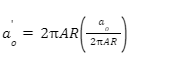
While using alongside lifting line in terms of estimating the raise slope of rectangular wing, the equation that is used is as follows:

- In this equation the AR: canopy aspects ratio
- In case of b2/S:b: canopy span and s: canopy area
- Τ: the parameter used in estimating rectangular platform
- The overall value of τ is ranging from 0.04 to 0.14 [for the aspect’s ratio of 1 to 5]
The lower aspect ratio is calculated through using the following equation
Th entire coefficient of the lift is stabilized which ranges from canopy ClThat can vary with di8fferent angles of attack, the α , in case of pre-stall process

While the entire detailed ratio is more than the value of 2.5, the above-mentioned equation is used in which zl is considered as the zero-raising angle of attack and the β is considered as arc-anhedral angle that is defined through Lingard.
In terms of estimating drag coefficient of duvet, there is profile drag of baseline air foil (Cd) is delivered that is added in approximately drag. Therefore, drag for the rectangular wing is delivered through

The used parameter δ is for the rectangular platform and it is considering as zero for the elliptical platform. In case of estimating value of δ it is seen that the value ranges from 0.003 to 0.037 in case of issue ratio of 1 to 5. On the other hand, in case of issue ratio of 3 the range is 0.018. In case of opening of principle case the concept of extra drag is taken into account. In which the drag coefficient is considered as the similar to one-half of opining pinnacle on duvet chord that is added toward expression in equation.
Suspension lines
Both round and non-circular strains created from a few materials are utilized as suspension strains in smash air parachutes. The Reynolds assortment of suspension strains in flight is typically on the request for thousands. Drag of inflexible round chambers in this Reynolds assortment extend is set one. Customarily, the overall span of the strains all things considered with the drag coefficient of one is utilized to evaluate the suspension line drag. In any case, suspension strains may likewise vibrate contingent upon the flight conditions and the pressure with inside the strains. Drag of vibrating strains might be obviously more than table certain strains. To decide the drag of suspension strains, first the table certain drag of strains is registered and afterward the more drag because of vibration is included. Blevins gives a technique to decide if or now not, at this point a circular chamber vibrates and the measure of the related drag increment. The technique for the assurance of the road drag is plot beneath.
As the direction of the strains with acknowledge to the approaching air stream decides the drag of the strains, the point θ normal with the asset of the use of each line area and the free stream accept the way things are must be resolved the utilization of the CAD model of the parachute framework. Hoerner demonstrates that the powers on an unbending chamber rely on the edge θ as follows:
Cd=Cdo Cl=Cdocos
At the point when the road is opposite to the drift, θ = 90°, the drag coefficient is Cdo, the standard worth, and the expansion coefficient is zero true to form. At the open door impediment of θ = zero°, the road is lined up with the drift, and lift and drag coefficients each evaporate. Obviously, the thick drag is dismissed in this restriction. For smash air parachutes, the benchmark drag coefficient is Cdo = 1. Knowing the direction of each line portion, the drag of all suspension strains underneath table certain conditions can be determined.
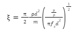
The proportion of regular recurrence to vortex losing recurrence of the suspension strains is a significant boundary in recognizing whether or now not, at this point the road portions of the suspension line instrument fall in a lock-in system in which vibration of the strains transforms into huge. To confirm the vibration of strains, the methodology noted in Blevins is followed in which it's far basic to understand the pressure, damping qualities, characteristic and losing frequencies of each line section. For each line fragment, the length l, distance across d, mass thickness m (mass reliable with unit length), strain T, line attitude θ, flexible modulus E, and the Poisson's proportion is required. The drift beat and liquid homes permit the road Reynolds number
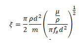
Also, the altered damping term 2πξ(2m/ρd^2). Both of these terms are dimensionless. The normal recurrence of each line portion is processed in the following condition expecting that the finishes of each line fragment are unbendingly held.

Here, n is the mode of vibration and under several conditions the principal n = 1 mode brings about the biggest amplitudes. Along these lines, just the major mode was thought of. To compute the characteristic recurrence of each line portion, the pressure in that fragment is required. Strain in each line stage can be resolved through way of technique for utilizing the strong. Computer aided design model of lines and a limited component based completely evaluation programming program programming bundle. In our work, we've utilized SolidWorks, a3D CAD programming program programming suite, to make the model and to complete the appraisal of the lines. The finishes of lines interfacing with the overhang, at a given attitude of assault, are thought to be held inflexibly, and a strain indistinguishable from the weight of the payload is practiced to the least period of the lines related with the conjunction point.
As such, the von Misses strain in each line stage can be registered utilizing the auxiliary appraisal instrument with inside the SolidWorks Simulation suite. The figured worries in each line stage permit the computation of strain, and thusly, the regular recurrence of that line stage. The machine for processing the not unordinary place drag of vibrating line portions is laid out in past figure. Two main questions should be replied. To start with, is the changed damping parameter2πξ (2m/ρd^2).the proportion of characteristic recurrence over the losing recurrence fall with inside the lock-in (synchronization) system? To address the subsequent one inquiry, the sufficiency of vibration Ay/d is required. Next figure offers the vibration plentifulness as a component of a damping boundary and the road l/d proportion.
As the road widths are little in appraisal to the length and the damping term inside side the abscissa is normally an extraordinary arrangement considerably less than one, the vibration sufficiency is taken to be Ay/d=1. Knowing the plentifulness, the lock-in go with inside the guide of the figure might be utilized to decide if or now not, at this point each line stage falls internal or outside of the synchronization system. In any case, the lock-in map in Blevins5 best stretches out as much as Ay/d ~ 0.5. This guide might be expanded through way of approach of transforming into a parabola to the information.

to be calculated,where ρ and µ are the air thickness and viscosity,respectively.Then,the vortex shedding recurrence fs for a fixed line is found from the Strouhal number
S= fsd/V∞.Strouhal number is a component of Reynolds number,and for the scope of boundaries experienced by smash air parachutes it is roughly steady at an estimation of 0.22.The vortex shedding recurrence is then given by fs= S V∞/d. The subsequent stage is to register the liquid damping term.
What's more, the adjusted damping term 2πξ (2m/ρd^2). Both of these terms are dimensionless. The normal recurrence of each line portion is processed in the following condition accepting that the closures of each line section are inflexibly held.

Here, n is the vibration mode and under most conditions the central n = 1 mode brings about the biggest amplitudes. In this way, just the major mode was thought of. To compute the common recurrence of each line section, the strain in that fragment is required. Strain in each line stage can be resolved through way of strategy for utilizing the strong CAD model of lines and a limited component based completely evaluation programming program programming bundle. In our work, we've utilized SolidWorks, a3D CAD programming program programming suite, to make the model and to complete the appraisal of the lines. The closures of lines interfacing with the overhang, at a given mentality of assault, are thought to be held inflexibly, and a strain indistinguishable from the weight of the payload is cultivated to the least period of the lines related with the conversion point. Thusly, the von Misses strain in each line stage can be registered utilizing the basic appraisal instrument with inside the SolidWorks Simulation suite. The processed worries in each line stage permit the estimation of pressure, and in this way, the normal recurrence of that line stage.
The machine for registering the not irregular spot drag of vibrating line fragments is illustrated in past figure. Two primary inquiries should be replied. To begin with, is the adjusted damping parameter2πξ(2m/ρd^2).the proportion of normal recurrence over the losing recurrence fall with inside the lock-in (synchronization) system? To address the subsequent one inquiry, the plentifulness of vibration Ay/d is required. Next figure offers the vibration plentifulness as a component of a damping boundary and the road l/d proportion.
As the road measurements are extremely little in evaluation to the length and the damping term with inside the abscissa is commonly an extraordinary arrangement substantially less than one, the vibration sufficiency is taken to be A_y/d=1 Knowing the plentifulness, the lock-in run with inside the guide of the figure might be utilized to decide if or now not, at this point each line stage falls inward or outside of the synchronization system. Be that as it may, the lock-in map in Blevins5 best stretches out as much as Ay/d ~ 0.5. This guide might be broadened through way of approach of transforming into a parabola to the information. The plot in figure beneath shows the road sections that fall with inside the lock-in system have characteristic frequencies among 0.4 and 1.6 occasions the losing recurrence. Inside this lock-in system, drag coefficient will blast to 3.1 because of the road vibration.

Outside this area, vortex losing does now not, at this point reason sizable vibration of the follows and the drag coefficient of the follows is relied upon to live simply like the table certain charge of one. As the duvet stacking alterations, the pressure with inside the follows changes, and thus, the normal recurrence of the street fragments adjustments. At the equivalent time the parachute flight speed depends upon at the framework stacking, and accordingly the losing recurrence of the follows adjustments with the stacking too. Since the proportion of the normal to losing recurrence is the indispensable segment boundary in distinguishing whether or now not, at this point each line stage falls internal or outside the lock-in system, tremendous explanations about the acclaim of the follows and their commitment to the overall drag of the framework can't be made. For each parachute framework and running condition, the investigation must be performed to build up the drag of each line portion and the complete line drag.
C. Sliders
To control the opening, ram-air shelters regularly gets fixed over the conjunction point after full expansion is accomplished. Sliders comprise of rectangular texture components held at the four corners. As far as anyone is concerned, there are no drag coefficient esteems in the writing for adaptable textures held under such conditions. To appraise the slider drag, drag coefficient of banners lined up with stream are thought of. It is comprehended that there are contrasts between a slider; however, we expect the drag coefficient stobe in a similar range.
Drag of a banner relies upon the viewpoint proportion and the texture territory. Hoerner gives a plot of the drag coefficient as an element of banner perspective proportion, see figure the harmony length is the measurement along the stream and the range is the cross over way. Smash air parachute sliders have viewpoint proportions normally short of what one. Assessment of a few smash air frameworks shows sliders have viewpoint proportions from around one to 0.36. The drag coefficient of banners with perspective proportions in this range is roughly 0.05. This worth is proposed as the slider drag coefficient, and the slider drag is processed utilizing the slider territory and the flight dynamic weight.
D. Payload
The payload for smash air can be people or freight bundles with parallely channeled geometries. For work force systems, drag on an individual is required. A first gauge is given by Hoerner where the drag zone is recorded as 9 sq. ft. for a "normal person “standing against the breeze. It is comprehended that the"average person" probably doesn't speak to a paratrooper, and the last will probably have a drag territory bigger than the worth gave by Hoerner. An elective technique is to follow the methodology illustrated in the work by Pen superintendent et al.The surface zone of a standing human is alluded to as
A_Du=0.0769W^0.425 H^0.725
Where W is the weight in Newton (N) and H is the stature in meter (m).Reference proposes a frontal region dependent on the DuBoisarea,A ≈ 0.35ADu. The drag coefficient dependent on frontal region. Thus, the drag territory would be:
AC_D=A_Du (An/A_Du)C_D=A_Du (0.35)(1.17)
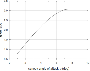
The discussions and points on this paper can be compared by those of others to come up with ways of developinThe cowl lift-to-drag (L/D) proportion become then processed through way of way of taking the proportion of the records withinside the figures. The subsequent cowl lift-to-drag proportion is reachable with inside the accompanying figure. The records in this plot imply that the blanket L/D differs with the outlook of assault, and it arrives at its most extreme cost at an attitude of α≈ 6.5°. The cowl lift-to-drag proportion of around 6 shows up more affordable for this model cowl at α = 7°.
The following stage becomes to process the drag of suspension strains. A model of the suspension strains permitted the quality of will of the direction of the road fragments with perceive to the approaching stream. The strains were expected to 2000-lb Spectra this is round with a distance across of 4 mm. From the start the strains were thought to be table sure (non-vibrating), and the overall drag of strains were figured utilizing a drag coefficient of one. The line haul under the table certain supposition become 463 N. At that point, the technique for the evaluation of line vibration provided the last section become followed. The guide delineating the vibrating strains from the table certain strains is tried underneath figure. Each line section is signified in my view in this guide. Most of strains fall with inside the lock-in system bringing about a major Cd. When the vibration of strains becomes considered, the overall line drag delayed to 1118 N. The vibration of strains delayed the road haul through way of way of a thing of 2.4 that could be a high commitment to the overall drag of the framework.

IV. Comparison of Ram-Air Parachutes
In order to compare the Ram-Air Parachutes, it is possible to review the distribution and distinct model. The cowl is considered in this case where it is assumed that the cowl area is smaller and the other huge that the model of Ram-Air Parachutes system within the previous phase. The smaller cowl parachute is considered as a loading of one of one psf within the same period of time as the larger cowl is assumed to load 3 psf. In this context, the model cowl load 2.2 psf with distinct loading system. Hence the same techniques are utilised to execute the model and compare Ram-Air Parachutes.
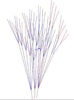
The figure considers the Schematic of stationary (red) and vibrating strains (blue). Which indicates the modifications of tension within the strains and there is frequency lines. In this context, the larger cowl system considers having better loading system as compared to the smaller cowl system, and the larger cowl indicates to shift the road segments towards right in the plot analogous in the figure.
In addition to this, the alternative system can reduce the road segment and shift it towards left due to smaller cowl system with lesser loading capacity.
It has also been seen that, the smaller variety of strains is associated with smaller cowl system, in the model and there is no such huge variety in the strains as compared to the model. Commutation of street drag can account to high line vibration which influences further to uniform and correlate with the duvet loading.
Accounting the vibration of lines inside the lock-in regime can be calculated and for the larger cowl system prolonged with the street drag by 5%. On the other hand, the small cowl parachute model is also utilised to drag the system with the purpose of street vibration. As per the comparisons of the model, there is 141% boom captured in section III.
The relative contribution of the street drag is examined efficiently for the times to be considered in this model. There is contribution of suspension lines by 35% which drag the model of parachute tool which is further evaluated in section III. In the larger cowl model, the lines are also effective to contribute in the model by 23% which is also dragged on the equal time with the lower loading 17% of the drag which is considered to be the suspension lines. This further implies that there is relative contribution of the street drag lines with quilt duration or loading right away. The parameters are effective fir describing the parachute tool and the mole indicates that the parachute formats are evaluated efficiently and uniquely in the system separately. On the basis of the ram-air parachute, it is not possible to generalise the comparison of the line vibration or the relative contribution of the street drag lines where overall performance must be examined separetly by considering each element in this model. In this regard, the quilt generates half of the whole drag system, three times which can be considered in this model.

V. Future Work (Hardware/Software Development)
The mechanical reeling tool and embedded prediction/control routine are effective to develop the vehicle prototype and the following sections are related to hardware and software program to explain the context.
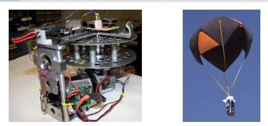
1. System of Mechanical Reeling
The figure below indicates the mechanical reeling tool and it is resembled a large electric powered sheng reel. It is capable to of sprucing off the parachute on a spool. The spool diameter can be adjusted to desire the motor torque and there are several payload masses to restrict the system. The high torque with 12V are assembled with the right angle gear box motor with a no load rotation fee of 116 RPM. The virtual speed controller mainly controls the whole system and it is delivered to efficaciously control the fee of motor. The reeling tools are burglars pod courtesy of Arturo’s UAV and the rotation of spool is measured by 10 bit continuous rotation absolute encoder. In the figure, the simple parachute tools are recognised to have further assembled.
2. Electrical System
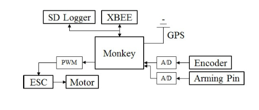
One of the effective computing platforms for the decent vehicles is a monkey cortex navigation platform (Ryan Mechatronics) which further includes GPS six service outputs, micro SD card logging, serial ports of man and women, IMU upgrades, barometric pressure sensor, ARM cortex processor and optical system which develop the whole system. The communication with all the sensors are pre-programmed as well as the C++ programming language is utilised in this context. The micro computer platform is efficient and very fast to handle the system as well as there are small robotics payloads to control the system. In addition to this, several electronics accessories are built in the system, with critical processing platform. The accessories have been incorporated efficiently to maintain virtual speed controller or ESC which is utilised in the power to the spool motor. On the other hand, the absolute encoder is also utilized to handle the motion of the spool. Air to ground communication is also completed efficiently with a XBEE-PRO XSC of modem (Digi).
The modems level up the conversation up to 28 miles which equals 45 km. a modified version of DIY drones Ardupilot is utilised in the ground station to enhance the activities of open delivered ground station software program application. The National Instruments Lab view is also considered to control the whole process and make it successful. Google earth is also contributing factor to process the software program application and it displays the data ADV tool facts for the ground crew. The tool is demonstrated by the figure below where is related to ground crew outlining the software program, application architectures.
The desired speed has been calculated in every second with the sensor at a frequency of 4-10 Hz and it depends on the specific sensor. The lesson error is associated and examined with the parachute reeling reactions and it is manipulated at a frequency of 10Hz.
VI. Discussion
The results indicate that there is descent control ranges and require significant actuator forces. The controllability of the methods are lower than the configuration and it further limits the descent strategy to be implemented while the speed changes. The installation cist of the added ring outweighs the increase in control while there is minimal increase in the descent speed controllability. The configurations are developed by A, B, C and D. As per the figure below, the configuration A and B need canopy reconfiguration as compared o the configuration C and D where C is two loop control line reefing and D is reeling based reefing. As there are excessive suspension lines, control line tangling during the descent phase as well as the reefing line, the added canopy payload complexities is introduced to manage the whole process.

The ring mountain is near the canopy and it is tangled with the suspension lines in the configuration B which is particularly a prone to tangling. According to the figure, the angle is the canopy suspension line is equal to zero of the control line is shortened. If it decreases, the control line will take more payload weight in the system.
The control line is effective to describe the payload weight and according to the drop test result, the control line load approaches 85% of the payload weight in the system. During the reefing, the lines are vertical and it is effective to provide sufficient inward force and furthermore it reduces the parachute wetted area.
The configuration B is intended to minimise the limitations and control the rigging complications due to tangling issues. This is related to the deficiency of the centre loop control line reefing technique.

As per the configuration D, it is reel based reefing technique which correlates the previous reeling based utilised for reefing autonomous decelerator vehicles flight results. The configuration B is intended to minimise the limitations and control the rigging complications due to the tangling issues. This is related to the deficiency of the centre loop and there is tremendous and effective as well as descent speed control mechanism under the reeling based reversible reefing system.
The limitations can be negligible under the small scale system, but full scale actuator is required to control the whole system. As per the analysis and findings, the study is effective to evaluate the reefing methods as compared to the reeling based approach and the system can be comparable between the large scale study and the measure the range with small scale system. Scalability and estimation are appropriate to manage the system and permit the comparison between the small scale reefing techniques.
Configuration C outperformed in the testing and estimation of the configurations and it results lower control line load and the descent speed controllable range. Maximum required actuator load of 2:5 N indicates 12% of payload weight. While analysing the system with its average controlling loads, the actual requirement is 5% of the payload weight. As per the findings, the reeling based counter art is larger than the full size parachute or the payload system. It is ideal control mechanism of the process which is further proportional to the change in descent speed. Ideal control mechanism is effective for the autonomous decelerator vehicles. As per the comparison, the canopies attached with the suspension lines and reeling based technique must be examined in the entire suspension lines for estimating the canopy diameter and understanding the loop system.

It is necessity to have clear understanding about the stability of the above mentioned various configuration with the steady state of behaviour. Stability analysis in configuration C is mandatory prior to the system and the history data on time provides some conservative confidence to the system. The canopy inflation may occur with the significant tangling suspension lines which may prevent canopy inflation from occurring.
VII. Conclusion
The above mentioned method and characteristics are developed and carried out to cover the aerodynamics characteristics with the willpower of the system. Slider and payload drag as well as the suspension line vibration and drag are laying crucial role to describe the whole system. Some of the proposed strategies are required to evaluate and gear up the whole system and computational process with the drag coefficient within the side. The aerodynamics float situation is being carried out in this study and the lifting line principles alongside with the computed CFD are beneficial to measure coefficient for covering the drag calculations. The drag coefficient analysis is helpful for this system to estimate drag of payload and slider. On the basis of above consequences of the study, the calculations are such as,
- 1. Contribution of the line drag is lower at 17% for the smaller version and it is high for the larger version with 35% in phase III. With the same concept, the drag growth is also increasing and decreasing with the larger and smaller version and it is 141% for high and for low it is %% of the inflexible line value.
- 2. The evaluation is carried out efficiently with practical parachute float ration and the parameters utilized for the sections.
- 3. For setting up the suspension line drag to machine drag it is mandatory to contribute and complete the evaluation of every character machinery desires. Cloth properties, length and type are also considered in this context to have clear orientation of every line phase with the coming float and distribution.
For further recommendations, it can be stated that, CAD is good and effective for advanced system to permit the inflated ram-air canopies and it is advanced system and extraordinary as compared to the cover inflates at the point of flight. The software of lifting the line principles and bring correct reductions are possible under the system, with CFD method and it is also beneficial to evaluate the small, low thing ratio that the canopies utilised for the employees and game leaning applications.
Take a deeper dive into Allocating Aid Budget to Mitigate Starvation and Refugee Crisis in Zamunda with our additional resources.


- 24/7 Customer Support
- 100% Customer Satisfaction
- No Privacy Violation
- Quick Services
- Subject Experts