Purpose and Types of Rebar Tie Wires
Chapter 1
1.1 Background Information
The purpose of tie wires is to hold the reinforcement bars in their right position before the concrete is poured. This essentially contributes to the stability of the rebar cages. The strength of the tie wire connections is thereafter of minimal concern after the concrete is poured. (Bules-Mejia et al, 2010). Normally, the most commonly used tie wires for rebar cages are made of black soft-annealed steel wires and fully annealed stainless steel wires. The minimum ultimate strength allowable for black soft-annealed steel wires is 276 MPa. In the market, one can find a variety of gauges, all the way from No. 16.5 to No. 14. Many fabricators are known to use 16.5 or the 16-gauge wire. Heavily reinforced structures may demand the use of the 15 or 14 gauge wire to stand the weight of the reinforcement bars. Tie wires are normally bought in about 1.5 kg coils, which the steel fixer can place in a tie wire reel and suspend it from his ironworker belt for convenience while using it. (CRSI, 2005). Stainless steel tie wires have a tensile strength ranging between 740-1150 MPa depending on the grade of the steel to be used. The 1.2mm stainless steel tie wire which is the most preferable size in UK will be used in this report. The advantage of using stainless steel is that it is strongly resistant to corrosion, it is possible to reduce the amount of concrete cover saving costs and time, and the metal can be recycled
1.2 Context
This thesis will cover the introduction part which gives a review of the types of tie wires available as well as their sizes. The literature review part gives information about literature that is available concerning tie wires and the studies that have been conducted concerning the tie wires. The next chapter is the methodology which outlines two methods that will be used to conduct the study. The first step will involve basic stiffness formulation for tie wires of different gauges. The second step will involve actual laboratory test to investigate the behaviour of tie wire connections under loading. The results and discussion section is the next part that will show the outcomes of the whole research using figures as well as written text. The final chapter will be a summary of the conclusions arrived at from the experimental results and recommendations on related items that were not covered in this particular study which may be picked up in future research works. An appendix is also provided at the very end of the report, with details of all the experimental data and results as obtained from the labs. There are no notable examples of available case studies showing failure of using strong tie wires. Perhaps this is because of the negative ramifications that exposure to such may bring on a project. In 2013, a crane was used to install a 12m x 7.5m prefabricated steel reinforcement cage wall which had 3 props secured in it to provide stability. As the preparation for installation of the shutter went on, one prop was removed. Upon an attempt to get rid of another prop, the cage collapsed and fell down. Fortunately, no injuries were recorded after the accident and a truss system was fitted over the starter bars in order to reinforce the cage and provide enough bending strength making it a permanent work instead of a temporary one.
1.3 Justification of the study
The purpose of this research is to establish the importance of using tie wires to reinforce cages during construction. When constructing a bridge or a building, tie connections are used on the reinforcement bars to create a strong rebar cage for the bridge or for the specific building. If this is not well observed, it may lead to future collapsing of structures because of the weak foundation. Bridges and buildings may get weak and collapse if they are not well reinforced and with time, they get weak and collapse. Back in the year 2012, the Health & Safety Executive in the United Kindgom confirmed over 200 onsite incidents concerning steel cages. Ten of these were collapses which inflicted serious injuries on the victims. And certainly these are not the only incidents. Numerous incidents have gone unreported worldwide. This is therefore a matter that requires investigation, to know the actual cause of failure, and how such failures can be prevented in the future. A thorough study of the behaviour of the steel cages in this temporary state must be conducted. Such study should preferably focus on both the global-scaling response, as well as at local areas (Kalfas, Camara and Mckinley, 2018).
Dig deeper into Advances in Embankment Stability with our selection of articles.
1.4 Objectives
To investigate the strength and stiffness of the tie wire connection. To assess the behaviour of tied wires under various type of loading. To investigate on different types and methods for tying reinforcement bars to identify the strength and stiffness of each method. To analyse the obtained data and compare it with theoretical one.
1.5 Scope of work
This study will begin with gathering of enough information by reading and collecting data from different resources including books, recent articles and educational magazines. The next step will be to carry out simple calculation of the strength and stiffness using a single tie wire with various diameters. In addition, the ultimate tensile strength will be identified from the manufacture products labels. The experiments in the laboratory will take a large percentage of the project. The first experiment will involve testing of single tie wire from numerous diameters using Tensile Testing Machine and comparing it with collected theoretical data. Using the same machine, the same test will be repeated by tying the reinforcement cage from one tie wrap to several snaps and calculate the strength and stiffness of each test. Other types and methods of tying the reinforcement cage and calculating their strength and stiffness will also be considered. After collecting all the data required, a deep data analysis of the laboratory data will be conducted and comparison done with other research data. The data will be manipulated in a number of ways, including plotting out, finding correlations, and making tables and graphs using Excel. Finally, the results will be interpreted and a meaningful conclusion made.
1.6 Gauges of tie wire
The table 1 below shows the diameter and cross sectional area of the different gauges of tie wire.

Chapter 2
2.1 Introduction
This section seeks to review past studies done by different researchers on the same topic. The information gathered from these past studies will give a good insight on what gaps exist in the study of the strength of tie wire connections. According to (Kalfas, Camara and Mckinley, 2018), the tying of the bars with wire has no effect on the strength of the final reinforced concrete structures. Even so, tying of the steel bars is very important when it comes to ensuring stability of the cages before concrete is poured. This enables lifting, handling and transportation of the steel cages without collapse or displacement of the steel bars. If the joints of the reinforcement cage were never tied together, then there would be free movement between the rebars. Such a cage would not have any rigidity. Tying is largely done by steel fixers. The steel fixers are known to have one of the most physically demanding jobs in the construction industry. However hard the job is, the tie wire connections are essential in the rebar cages to ensure that the minimum concrete cover over the rebars is maintained. This further prevents erosion of the steel reinforcement bars and therefore promotes durability of the structure. The tie wire connections also prevent displacement of the reinforcement bars as construction activities go on around the rebar cages. Such activities may include laying of electric conduits and plumbing fixtures.
2.1 Types of Tie Wire Connections
There are a number of methods used to tie reinforcement bars. The Concrete Reinforcing Steel Institute identified five of the main methods used for tie wire connections. These are outlined below:
Slash and double slash tie
Wrap and snap
Saddle - single and double-u
Wrap and saddle
Crown tie
Various iron workers have adopted their own preferred styles for tying reinforcement bars. The most common methods among steel fixers are single-snap, double snap, single-U, double-U, column tie, wrap and saddle, and strong tie. Each of the above mentioned methods has a specific way of tying together the reinforcement bars. The tying process is however similar for all the methods. The bottom line for all these methods is that the two free ends of the tie wire must come together and be twisted until they firmly hold the reinforcement bars. The steel fabricator must take caution not to excessively twist the tie wire, so as to avoid breakage of the wire. The more experienced steel fixers can achieve the right fit without much struggle. The less experienced steel fixers may produce either loose or excessively tight connections. According to (Kalfas, Camara and Mckinley, 2018), an experienced steel fixer increases the stiffness and capacity of the connections by 196% and 18 % respectively. Also, the cage stiffness and capacity improves greatly when a greater number of bar intersections are tied, and the stronger tie wire techniques are employed.

Slash Tie
The single and double slash ties are mostly used where the force of the concrete interacting with the reinforcement bars is minimal, and the shifting of rebars either longitudinally or vertically is not expected.
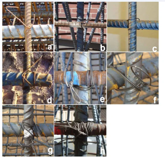
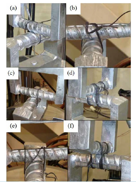
Single Slash Tie - This can be said to be the easiest and most straightforward tie wire connection. The crossing point of the rebars is diagonally wrapped once. Figure 2. a below illustrates this connection.
Double Slash Tie - This is a stronger version of the single snap, produced by doubling the wire. The figure 2b below illustrates this type of connection.
Hairpin tie
This is a more advanced connection than the single snap, hence it can consume a slightly longer time to make it, and of course forms a stronger tie. The tie wire is rounded on the bottom bar, the two free ends rounded on the crossing bar, and finally twisted together around the first bar where the U started. Figure 2c below illustrates this type of connection.
Hairpin tie with ring
This is a stronger version of the single-U tie wire connection, formed by doubling the wire and making the U connection as described above. Figure 2e below illustrates this type of connection:
Wrap-and-Saddle
This closely resembles the double-u tie wire connection, only that the first bar receives an extra wrap, as illustrated in fig 2f below:
Crown tie
For this tie wire connection, the crossing point of the rebars is diagonally wrapped twice, to form an X-shape that resembles the number 8. This type of connection is illustrated in figure 7 below: The wrap-and-saddle, figure-eight and double-U tie connections can be well categorized as the more complicated ties. These are appropriate where more strength is needed to hold the rebars in their right position as concrete is placed.
Column tie
This is a combination of the single-U and single-snap tie wire connections. It starts out as a single-U but then one of the free ends is tied diagonally before twisting and healing. The figure 8 below illustrates this type of connection.
Strong Tie
This is fashioned in the same manner as the double-U connection, but the tie wire is wrapped more than three times. This is made in specific intersections of rebars that require strong connections, especially at the initial stages of setting up the cage. There is no specific way of making this connection. The bottom line is that it has to be strong. The figure 9 below illustrates this type of connection.
Wrap-and-snap
This tie wire connection is formed by wrapping the tie wire around the first bar, followed by a diagonal wrap around the crossing bar. The ends of the tie wire are twisted and healed in similar fashion to the snap tie. As such, this tie wire connection is not strong enough for setting up column rebar cages.
Splice tie
This tie is used with individual reinforcing bars with an aim of transmitting forces through a certain structure hence creating a load path. In this type of tie, the engineer gives details of location, lap length and all the details that are related to structural drawings in order to avoid technical mishaps In a study by Appadurai (2016), two different tying techniques were investigated. The tie wires were subjected to out of plane pulling, first using single wires, and then using double wires. This was repeated three times for each sample. It was concluded that the strength of the connection doubles when the double slash technique is used, as opposed to the single slash. In another study by Shevlin (2016), the following equation was proposed to calculate the capacity of the tie wire connections around reinforcement bars. Fd = Varfactor*K*Wmin.tensile Where: Fd (N) is the analytical tie capacity due to out-of-plane pulling and tangential sliding of crossing bars. Varfactor is the factor that considers the wire material and the loading condition K is the number of wire lengths wrapped around the intersection Wmin.tensile(N) is the minimum failure load provided by the manufacturer. With this formula, the structural engineers would know the important joints within the reinforcement cages, depending on the forces the joints were foreseen to undergo. These forces would depend on the method of installation of the rebar cage. , By knowing these forces, the structural engineers would also be able to determine the tying requirements of the joints such that they would withstand the forces (Shevlin, 2016). The journal Stability of Reinforcement Cages prior to Concreting (2013) lists inadequate strength of tied joints as one of the leading causes of cage instability during installation and erection. It details the factors which affect the strength and capacity of tied joints. These factors include, but are not limited to: how tight the tie is, the number of ties, the tying pattern, the number of twists, the number of reinforcement bars, the size of reinforcement bars, and the tie wire material. However, the journal does not provide any quantitative information on what affects the strength of tied joints, and how that particular factor affects the strength. This has left engineers and contractors with little solid information on tying reinforcement bars. AMEC Civil Engineering Limited (1994) also conducted a research on tie wire connections. 5 lab tests were done on 32 mm diameter rebars tied using 16g SWG double tie wire. They tested both tie configuration and rebar setup. Multiple joints were loaded until failure occurred. One shortcoming of this experiment was that each test was repeated only once and so the results were limited in a way. Secondly, only one type of tie wire material was used. Thirdly, only 2 tying techniques were used, whereas steel fixers use around 6 common types. Lastly, the tie wires were all doubled, and so the behaviour of single tie wire connections was not taken into account. The above four factors made this test by AMEC Civil Engineering Limited quite limited in scope inadequate in comprehensiveness.
2.2 Distribution of tie wire connections in rebar cages
There is no specific pattern in which to spread out the tie wire connections in any rebar cage. The CRSI in their journal Placing Reinforcing Bars states that tying of reinforcing bars is just a means to hold them in their right position as other specialists work around the rebar cages, and finally during the placement of concrete. They further state that it is not a must to have tie wire connections at each and every intersection. This is because tie connections have no influence on the strength of the end product - the reinforced concrete structure. (CRSI, 2005) The steel fixer’s job should be taken very seriously. Incorrect positioning of the reinforcement bars may lead to a catastrophic concrete failure. For instance, lowering the top bars by 25 mm or raising the bottom bars by the same margin for a slab could decrease its load carrying capacity by 20%. (CRSI, 2005)
2.3 Effects of Cage Failures
Cages have a large size and massive weights. As a result of this, they do not need to be moved or lifted from one place to another often. However, there are structures which require reinforcement cages to be made from the ground and then lifted or rotated into the desired position. This process should be handled with great care because it doesn’t matter whether these cages are constructed on-site on off-site, they are prone to collapsing in the process of erecting or installing them (Shevlin, 2016). In most cases, cages fail when being lifted or rotated and also when they have been secured in place before concreting as a result of stabilization by a shutter. The failures are as a result of internal cage forces, loss of cage strength and unstable cages. Failure of cages is very dangerous to the people working with them as they may cause serious injuries. Some of the cage collapsing cases are fatal. According to Shevlin, (2016), failure of the cages may lead to project delays as there is some time taken to adjust the cage again and need for hunting new workmanship if the initial workers were hurt in the process. Extra costs are also incurred as the process needs to be done again and new materials need to be bought and put in place. Cage failures are overly expensive in terms of costs and human life and wellbeing.
2.4 New technology and trends
Steel fixers have long made tie wire connections manually using the conventional hook or the hand twister. However, in recent years, the tie gun has revolutionized the steel fixing trade. The tie gun considerably lessens the physical demand on the part of the steel fixer. Using a tie gun for tie wire connections also saves on material due to its precise nature of twisting and cutting the tie wire. Most importantly, the tie gun saves a lot of time which would have otherwise been spent on steel fixing. (JOSE, 2007)
Strength and stiffness of tie wire connections
The connection of tie wire consists of wraps of wire around the bars that are being connected. The mechanical properties of tie wires comes to play when some gravitational or external forces try to displace the reinforcement bars. (Bules-Mejia et al, 2010)
2.5 Effect of workmanship
Workmanship is known to have an influence on the strength of the tie connections. To investigate the effect of workmanship, the total number of specimens in an experiment is normally divided into two groups. An experienced steel fixer makes the tie wire connections for the first group, whereas an inexperienced steel fixer makes the connections for the second group of samples.
Chapter 3
3.1 Introduction
This study will be carried out in two basic steps. The first step has already been done, but the second step is what will be done from now henceforth. The first step involved basic stiffness formulation for tie wires of different gauges. The second step will involve actual laboratory test to investigate the behaviour of tie wire connections under loading.
3.2 Analytical approach
Stiffness is defined as the property of a material which makes it rigid and difficult to bend. The formula for axial stiffness is expressed as:
k = F/(FL/AE)
k = FAE/FL
k = AE/L
Where:
A is the cross sectional area of the tie wire
L is the length of the tie wire - three scenarios are considered for the length of the tie wire (top-bottom, mid of the two bars, and outer length)
F is the applied force
E is the elastic modulus of the tie wire
For the purpose of this study, the maximum modulus of elasticity of steel is taken as 210 GPa, a figure which my project supervisor, Dr. McKinley proposed. The same also proposed the minimum modulus of elasticity to be taken as half the value of the maximum - this comes to 105 GPa Having the values of A, E and L, the stiffness of the tie wires can easily be computed by substituting these values into the stiffness formula.
3.3 The experimental approach
The laboratory tests involved the determination of the ultimate strength of tie wire connections with various diameters and different tie configurations. The Instron tensile testing machine was used for this purpose. Below is a brief description of how the machine operates.
3.3.1 The Instron testing machine
The first step is to check whether the load cell is correctly installed. the load cell should be 100kN. In case a wrong load cell is installed, remove it and replace it with the correct load cell carefully. There are six head screws which should be tightened in a star manner like a car tire and then the cell is collected to the frame. Calibrate the load cell using a dialog known as Bluehill.
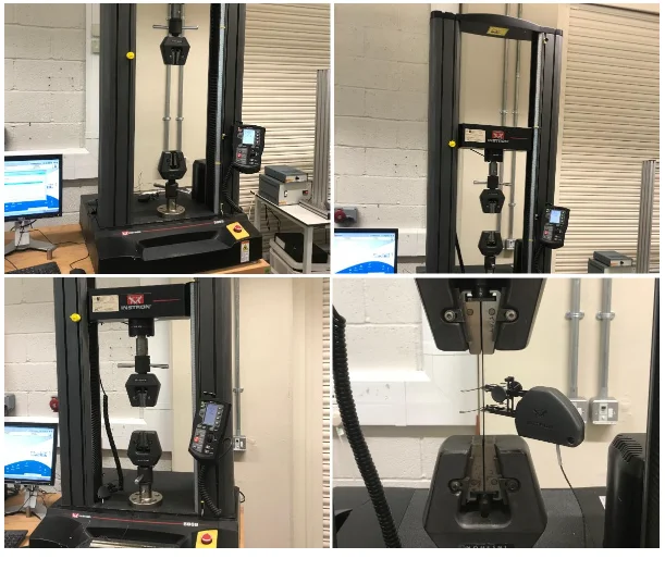
Next, install the correct features for your test and in a case where tensile grips are being used, install the adapter first and then install the grips and then tighten them. Open Bluehill test and verify the parameters that you want to use in your method. Be careful not to tamper with the load cell calibrations. Next, install the specimen and using the fine adjustment knob, use a small load to get rid of any slack. If necessary, tighten the grip adjustments and then use the fine adjust to get close to zero as much as you can. To ensure safety, put down the protective shield and then wear your safety glasses. You are now good to begin the test. Once you are done with the test, load the next sample and then click on the finish button. If you are through with the test method, select the second finish button and a dialog will pop up asking if you want to start a new test using the same methods. If that is the case, then say yes and then a new file will be opened. If you do not want to, select no and then exit bluehill. Finally, remove your data from the desktop to a USB drive. Always remember to place your broken samples in a trash receptacle once you finish using the machine.
3.3.2 The laboratory experiments
3.3.2.1 Experiment 1
The first activity in the laboratory involved testing of two soft black annealed tie wires of diameters 1.5 mm and 1.6 mm. These were tested for elongation and yield strength. 5 samples were used for each gauge of tie wire. The samples were named Coupon 1, Coupon 2, Coupon 3, Coupon 4, Coupon 5. The above procedure was repeated for 5 samples of 1.2 mm diameter stainless steel wire.
Experiment 2
The next experiment involved tying two 16 mm parallel reinforcement bars on the plain area using the 1.6 mm soft black annealed tie wire. 5 ties were made using single loops, and another 5 using double loops. The sample was subjected to the tensile testing machine to test the yield strength. The above process was repeated with the 1.5 mm diameter soft black annealed tie wires, and finally with the 1.2 mm diameter stainless steel wire. For the 1.5 mm diameter soft black annealed tie wire, 5 samples of single loops were used. The double loops were not considered. For the 1.2 mm diameter stainless steel tie wire, 10 samples were used, all single loops.
Experiment 3
The next experiment involved two 16 mm parallel reinforcement bars tied on the ribbed area. The 1.6 mm diameter soft black annealed wire was used for tying. 5 samples were used here, all single loops. The pre-stress strength values were recorded for puposes of comparison.
Experiment 4
The next experiment involved tying two 16 mm reinforcement bars perpendicular to each other and tying them on the plain area. The 1.6 mm diameter soft annealed tie wire was used tying. Three tying techniques were tested herein: the single-slash; the double slash and the hairpin. For each of these techniques, 5 samples were used for purposes of averaging .
Experiment 5
The final experiment involved tying two 40 mm reinforcement bars in parallel. The 1.6 mm diameter soft black annealed tie wire was used. 5 single loop samples were tested, followed by 5 double loop samples.
3.4 Ultimate strength of tie wire connections
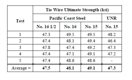
In rebar cages, the main purpose of the tie wires is to hold the reinforcing bars in their right position before concrete is placed in and around the cage. The strength of the tie wire is of no significance after the concrete is poured. The tie wires only make sure the rebar cage maintains its stability before the concrete is poured. The erection of the rebar cages may exert some force on the reinforcement bars, in such a manner that the bars tend to move away from each other, or one bar moves in a rotary motion in relation to the intersecting bar. This is where the mechanical properties of the tie wires come into play. If the forces acting on the rebars exceed the ultimate strength of the tie wire connections, the tie wires may snap and fail in shear. Other modes of failure such as tensile failure may also be witnessed. The ultimate strengths for the above mentioned gauges of tie wire were experimentally determined by a steel contractor based in Fairfield, California, by the name Pacific Coast Steel. These values of ultimate strength are presented in the table 2 below.
3.5 Stress-strain response of steel wires
To determine the stress-strain relationship of the steel tie wires, a series of tensile tests will be conducted according to ASTM-370 procedure. The tensile tests will be performed on the Instron loading frame fitted with displacement controls. The tie wire samples will be wrapped around the loading frame and two threaded rods. A diagonal hole with a slightly larger diameter than the tie wire will be drilled at the mid point of the cross section to one side of each of the rods. The free ends of the tie wires will then be inserted through the drill holes and wrapped around the rods to strongly attach them. The length of the sample tie wires will be around 635 mm, with a final straight length between rods of 230 mm. The control knobs will then be turned on. The tie wires are expected to immediately start experiencing some deformation. This deformation will be measured using an Epsilon axial extensometer with 200 mm gauge length which allows the recording of the entire stress strain curve up to the point of failure. The load applied will be basically a 2268 kg axial load cell. Figure 11 below illustrates this set up.
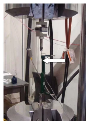
The tie wire connections will be modeled with non-linear translational trusses (Fig 4) and non-linear rotational springs (Fig 5). The vertical and horizontal elements of the trusses represent the longitudinal and transverse bars of the rebar cages. This adequately represents the local model of tie wire connections. The following three forces will be analyzed:
A large displacement force applied to all the members A small displacement force applied to all the members A large displacement force applied to the beam and a small displacement force to the truss elements.
The test will be set up to mimic the actual intersection between reinforcement bars. The set up will include two C-shaped steel frames with reinforcement bars welded onto them. The normal translational (dx) direction of the tie wire connection will be investigated by welding the bars perpendicular to each other.
To test the tangential (dy) and vertical (dz) translational displacements, a seperate set up will be made, as illustrated in figure 14 below.
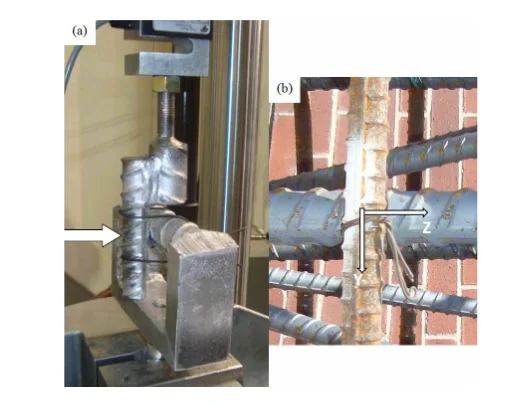
The C-shaped frame with the Y11 bar welded onto it will be fixed to the bottom grip of the loading frame. A Y8 bar will then be tied vertically to the Y11 bar, and and fixed to the top grip of the loading frame. An upward displacement will be applied to the Y8 bar to test the dz and dy displacements. The displacement transducer will be used to record the deformation data. The displacement rate will be set at around 0.25 mm per second. The figure 15 below shows the analytical model of the proposed forces acting on the rebars:

Chapter 4
4.1 Introduction
This chapter sets out the key experimental results, both theoretical and from experimental results. The methods followed to obtain these results are discussed in the preceding chapter 3.
4.2 Theoretical Results
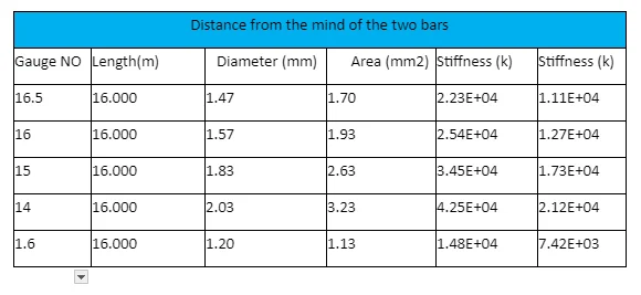
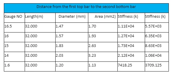
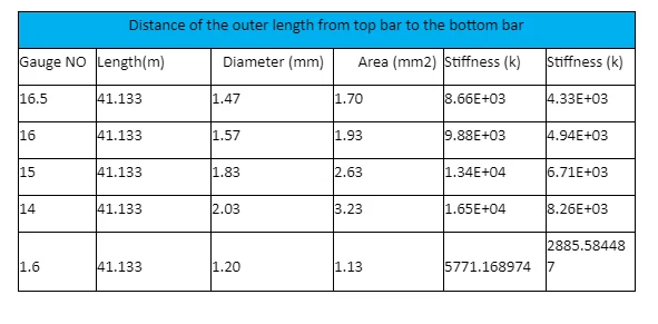
The table below shows the stiffness values for a tie wire wrapped around Y14 reinforcement bars. The values for other sizes of bars are detailed in Appendix B.
Chapter 5
5.1 Introduction
In this chapter, the results obtained both theoretically and from the experiment shall be discussed herein. An analysis of the results shall also be presented.
5.2 Theoretical approaches
The graph below was plotted using the calculated values of stiffness, considering the distance between the middle points of the two intersecting bars:

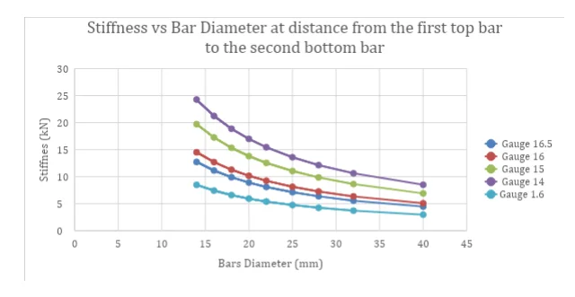
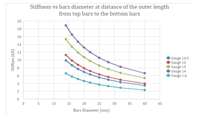
From the graph, it can clearly be seen that the longer the tie wire, the less the stiffness. In other words, the stiffness of the tie wire is indirectly proportional to the length of the wire. Another evident observation is the increase in stiffness with increase in cross sectional area of the tie wire. The 14 gauge tie wire has the largest cross sectional area, whereas the 16.5 gauge tie wire has the smallest cross sectional area. As such the 14 gauge tie wire exhibits higher values of stiffness for a given length of wire, compared to the 16.5 gauge tie wire. Two other graphs were plotted considering the distance from the top of the first bar to the bottom of the second bar, followed by the circumferential distance from the top bar to the bottom bar. The two graphs have a more or less similar shape to the first graph discussed above.
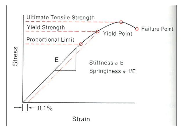
A normal stress-strain curve for steel would look like the one in figure 19 below. This confirms my conclusion on the indirect proportionality between the stiffness and length of the steel tie wire connection
5.3 Experimental approach
From the results obtained from the laboratory testing with the Instron Tensile Testing Machine, the following graphs were plotted.
5.3.1 Part 1 - Types of tie wires - Materials and sizes
5.3.1.1 Graph of 1.5 mm diameter SBA tie wire
The graph below shows the force applied vs displacement curve of 1.5 mm soft black annealed tie wires.

Generally, the deformation of steel is directly proportional to the load applied. When the steel attains the elastic limit, it starts deforming at a higher rate for a given load value. The steel then undergoes strain hardening, where little increments in the load cause a considerable deformation. Strain hardening leads to fracture and eventually failure of the material. The figure below shows the load displacement relationship for the 1.6 mm soft black annealed tie wire.
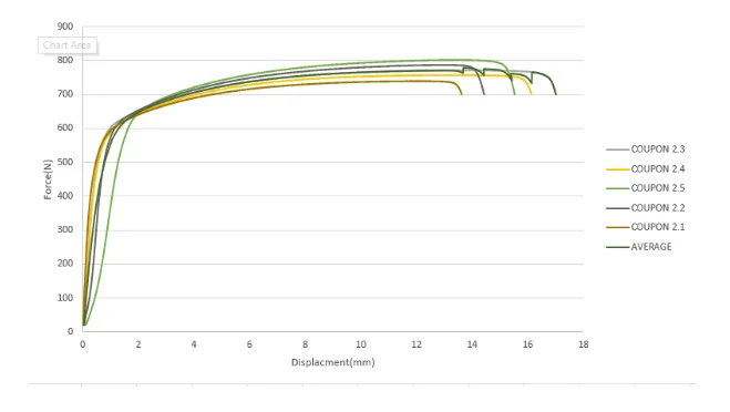
The ultimate strength for the 1.6 mm diameter tie wires is roughly 750 N, whereas for the 1.5 mm diameter wire is roughly 600 N. The larger the cross sectional area of steel the higher the yield strength. The coupon 2.2 is less stiff as compared to the other 4 samples. This could be attributed to an accidental slip on the jaw of the wires.
5.3.1.2 Graph of 1.2 mm SS tie wire
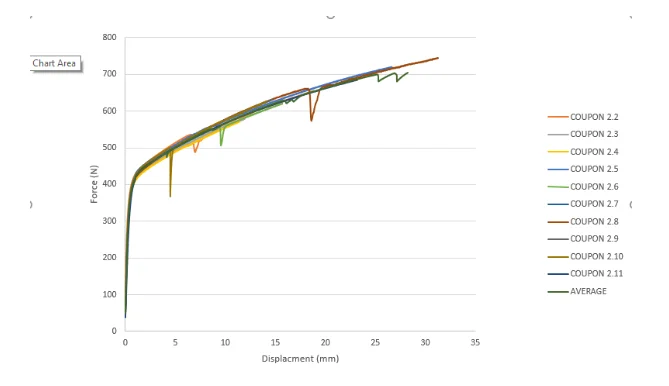
Coupon 2.8 exhibits some sudden reduction of load with no change in displacement. This could be attributed to a slip of the wire while under test. The three graphs above do not exhibit any displacement as the load increases from zero up to a certain point. This is because the load must first straighten and tighten the wires before the wire starts deforming. The graph below combines the averages from the above three graphs, to compare the load displacement relationship of the 3 tie wires under investigation.
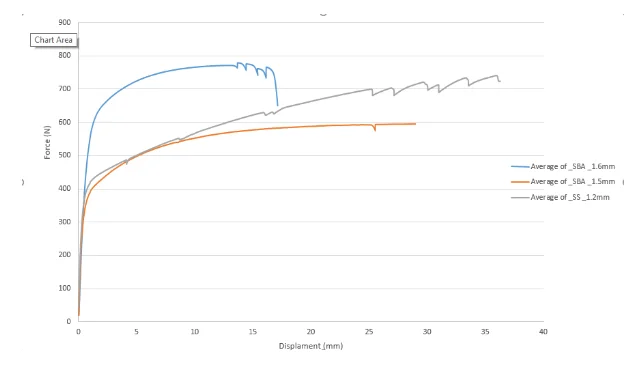
It is evident that the 1.6 mm diameter SBA tie wire has the highest ultimate strength. The 1.55 mm SBA tie wire has the lowest ultimate strength. The graph above can be modified to compare the stress strain relationship for the 3 tie wires under investigation. The graph below shows the results.
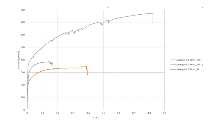
The graph reveals that the 1.2 mm diameter stainless steel tie wire is the stiffest of the three. The 1.6 mm diameter SBA tie wire is again stiffer than the 1.5 mm diameter wire. Though the two are of the same material, the differ in cross sectional area, and that is the reason for the difference in stiffness. The below graph is a further modification of the average stress vs strain values of the 3 tie wires, but with a smaller strain range to be able to compare stiffness. The conclusions on stiffness just mentioned above are confirmed in this graph also.

The change in the gradient of the (SS) wires after 0.1 strain is called strain hardening. For part two and three, failure was considered when one of the following happened:
Distance from the bars got greater than 20mm. Failure of the wired connections i.e. (breaking of the wire samples) Where there was 20% decrease of the applied load prior to failure.
5.3.2 Part two - 16mm bars in parallel
The second part involved tests on the 16mm bars in three ways.
The bars parallel and tied on the plain area The bars parallel and tied on the ribbed area The bars perpendicular to each other and tied on the plain area
The graphs for these tests are presented below:
# The bars parallel and tied on the plain area
Below is the graph obtained when using 1.6mm (SBA) gauge tie wire (single loop).
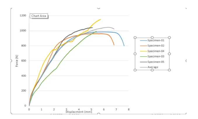
It is evident that the Specimen-03 does not have equal values of displacement with rest. This unusual behaviour may be attributed to the following:
Possible slip of wire over rib. Tie unwinding.
Below is a graph for a repeat of the above experiment, but now with double looped tie wires.
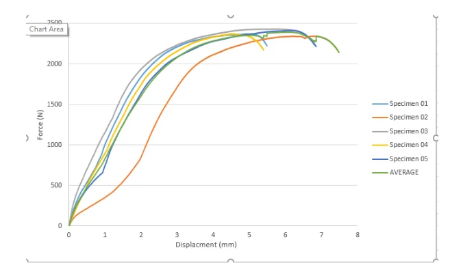
The unusual behaviour of Specimen 02 in figures 8 above could attribute to one of the loops being loose. The graph below compares the averages of load vs displacement relationship for the single and double loop experiments with the 16 mm bars tied parallel to each other.
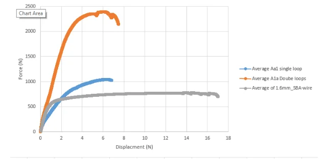
Notice the distinct difference in ultimate strength. The double loop exhibits greater strength and stiffness than the single loop system. The load displacement relationship for the 1.6 mm SBA tie wire is also included in the graph. It is evident that the capacity of the tie wire increases when tied around the bars, as opposed to when it is loaded in isolation. Below is the graph for the same 16mm bars tied in parallel on the plain area, but this time with a single loop 1.5 mm SBA tie wire.
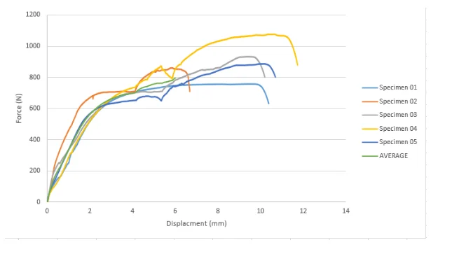
In this experiment, no specimen exhibited strange behaviour in relation to the rest. Below is the graph obtained for the experiment with parallel 16mm bars tied on a plain area with single loops of 1.2mm (SS) gauge tie wire.

Likewise, in this particular experiment, no specimen exhibited noticeably strange behaviour in relation to the rest The above three graphs can be averaged and combined to yield the following:
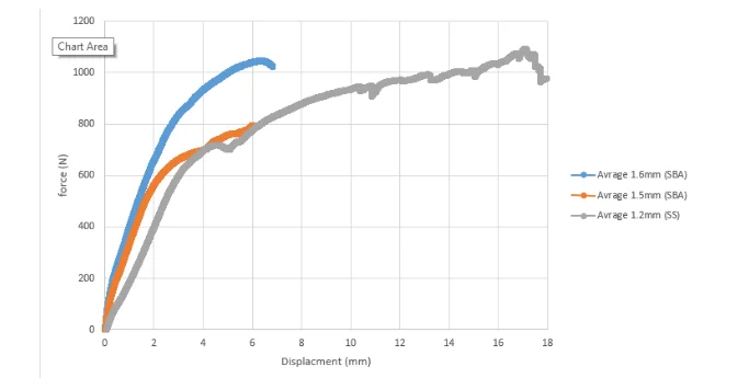
The 1.2 mm SS tie wire has the highest capacity, followed by the 1.6 mm SBA tie wire, and finally the 1.5 mm SBA tie wire.
The bars parallel and tying on the Ribbed area
The graph below shows the result of tying the 16mm bars in parallel with single looped 1.6mm (SBA) tie wire on the ribbed area.

The average ultimate strength in this setup is about 1000/5 N/mm. The graph below compares the tie wire connection capacity when tying the 16mm rebars in parallel with 1.6mm diameter tie wires, first on the plain area (A1a) and secondly on the ribbed area(A2a), with Single loops.

When tied on the rib area, failure occurs faster than when the rebars are tied on the plain area. The ribs are wrapped tightly by the tie wires, making the tie wires rigid upon application of a force, in such a way that they snap immediately when force exceeds a given minimum.
The bars at 90 degree and tied on the plain area
Below are three graphs obtained when the 16mm rebars are tied at 90 degree to each other with the 1.6mm (SBA) tie wire using three different techniques..
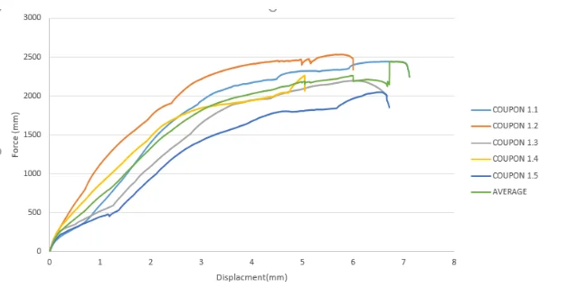
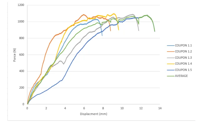
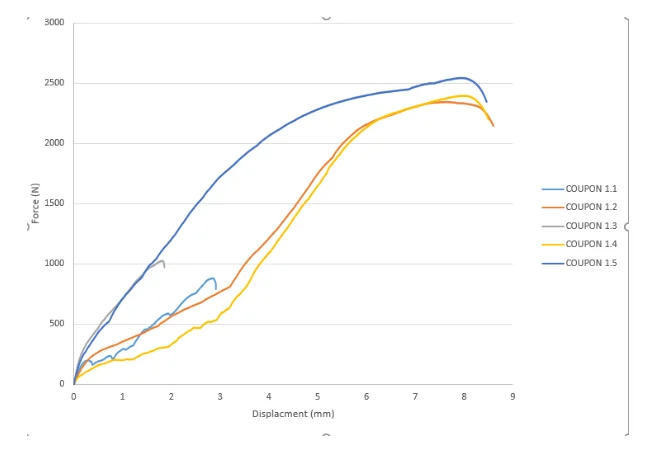

The averages from the three graphs above can be combined to come up with the below comparative graph.
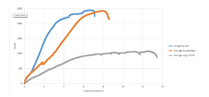
The hairpin technique can be seen as the most effective, followed by the double-slash, and finally the single slash.
Part three 40mm bars in parallel)
The 2 graphs below were obtained when the 40mm bars was tied in parallel on the plain area using the 1.6mm diameter tie wire (SBA), first in single loops, and secondly in double loops.
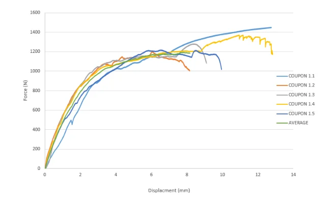
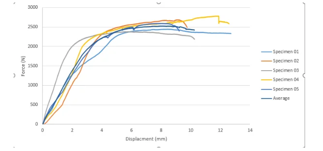
The graph below compares values of the two graphs above, and also with the load - displacement relationship for the single 1.6mm tie wire.

It is clearly evident that the double loop provides a stronger tie wire connection than the single loop. Doubling the cross section area doubles the force required to bring the specimen to fail.and see what’s the percentage increase is the max force with single loop and double loops when comparing with single loops Finally the graph below compares the load-displacement relationships for tying 16 mm and 40 mm rebars, using double loops of the 1.6 mm SBA tie wire.

It can be seen that the tie around around the 40mm rebar fails first. This can be attributed to the larger forces exerted by the internal and external forces of the 40 mm rebar, as opposed to those in the 16 mm rebar.
References
AMEC Civil Engineering Limited, EPS2 Contract (93/118), Sellafield, Test report, Site test of proposed tying wire connections of T32 reinforcing bars to be used for supporting stop ends to vault roof pours, A. L Newton, A. L Stubbs, J O’Rourke, J. Napier, (1994).
Appadurai S. The stability of reinforcement cages prior to concreting. London, UK: City, University of London; 2016.
Builes-Mejia J. C.,Itani, A.M., Sedarat, H. , 2010, Stability of Bridge Column Rebar Cages during Construction.
Caltrans, 2006. Standard Specifications. California Department of Transportation, Sacramento, CA.
Condon-Johnson & Associates, Inc, 2008. Reinforcement Submittal – CIDH Rebar Cage. San Diego, CA
CRSI, Concrete Reinforcing Steel Institute, 2005. Placing Reinforcing Bars (8th Edition). CRSI, Schaumburg, IL.
Kalfas, K., Camara, A. and Mckinley, B. (2018). Numerical analysis of wired connections of the reinforcement bars of steel cages: the slash tying technique. 40th IABSE Symposium.
Shevlin, G. (2016). Design Strength/Capacity Joints in Steel Reinforcement Cages. Undergraduate. Queen's University Belfast.
Temporary Works Forum, Stability of Reinforcement Cages Prior to Concreting,TWf2013: 01, (2013)
- 24/7 Customer Support
- 100% Customer Satisfaction
- No Privacy Violation
- Quick Services
- Subject Experts


