DC Motor Transfer Function Creation
The open-loop response of dc motor to a step input
The first step was to create the DC motor transfer function. In order to do this, a transfer function object was created using the tf(‘s’) function. The values of the gain and time constant were then declared and the transfer function has been created by using the tf() function together, with the declared numerator and denominator values. The step() function was then utilized to plot the open loop step response for the DC motor, shown in figure 1.
The steady state value of the response shown in figure 1 is 0.1 and this is much lower than the input value of unity. The offset between the two values is 0.9 and this error is usually undesirable. A feedback loop and a controller can be added to the system to eliminate this error.
Tune P,PI and PID controllers
In this subtask, a controller was designed by using pidtune() function and feedback, introduced into the system using feedback() function. The pidtune() function was utilized to model a P only controller, a PI controller and a PID controller. The PID controller had three options, which were modeled. These are: balanced, reference tracking and disturbance rejection options.
Open loop response and Tune P,PI and PID controllers were opened by using the code below,
Subtask 3: Hydraulic Brake Actuator Design
The hydraulic brake actuator of the turbine’s open-loop transfer function is given as:
Fs=1/s+10s+2 (10)

The task is to design a controller of the type s+as+b where a b. The settling time is specified at 13seconds and the damping ratio as 0.707.
Dig deeper into Wireless Power Transfer with our selection of articles.
The percent overshoot can be determined from the damping ratio using[2]
% Overshoot=e-ζπ1-2*100 11
% overshoot=e-(0.707*π1-0.7072)*100=4.33 % (12)
The Control System Designer was opened using the code below[3]
Running the code above opens both bode editor and root locus editor and the closed loop step response shown in figure 5.

The step response in figure 5 has a final value of 0.048, a settling time of 1.95seconds and zero percent overshoot. The first step is to make the step response have a final value of 1. In order to achieve this, lead compensator is added to the root locus editor for getting further response, shown in figure 6.


In figure 6, the step response has a final value of 1.15, a settling time of 0.397 seconds with high overshoot. It has still not met the requirements. At this stage, the compensator has the form.

In order to meet the requirements of the compensator, manually manipulating the gain and zero and pole locations on the compensator editor to be in the intersection between the two requirements setting time and damping ratio, the response obtained is shown in figure 8.

In figure 8, it can be seen that the step response has a settling time of 0.337 seconds and no overshoot meet the requirements as shown above. The pole and zero positions and the gain of the compensator for the response are provided in figure 9.

TASK 2: Wind Turbine Simulation
This task is working on designing a Simulink diagram for wind turbine, and there were requirements for the design, which must be followed according to the different design conditions, so that the most important of them were the stability (fixed) and change of the speed and direction of the wind. Creating a subsystem that used for the conversion wind speed into an angle, and creating a subsystem that used for the DC motor from the Simulink Diagram are shown below,
Wind turbines are utilized to harness wind energy. They consist of a generator, a nacelle, the tower structure, rotor blades, low-speed rotor, a high-speed shaft and a low-speed shaft that are mechanically coupled through a gearbox assembly, a wind vane indicator, a yaw motor drive assembly and a pitch motor drive assembly [4]. Pitch and yaw are the two factors that control the blade angle and the turbine rotation respectively for the wind turbine and in addition, the wind speed is related to the Pitch angle, and the wind direction is related to the yaw angle as show below,
The model of the Simulink of the wind turbine consists of conversion,

The speed and direction of the wind changes, so that the wind turbine utilize anemometer, which are devices measuring wind speed and direction such as wind monitor Wind Monitor.

Contents of Wind Turbine Simulation System
Overview of the overall model
Dc motor subsystem
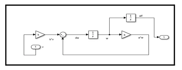
Since the pitch and yaw mechanisms are constructed around motors, their mechanical mathematical representation is given as:
dω/dt=kv-aω
Where v is the input voltage to the motor, the angular speed of the motor shaft, and k the motor constant which is equivalent to 0.4, and a which is equivalent to 4.
The DC motor representation in the above equation is modelled in Simulink as shown in Figure 3,
From the system modelled, the motor’s angle of rotation is directly proportional to the blade pitch angle. is therefore given by:
α=k1*β
Where is double therefore the gear ratio of the Dc motor is equal to 0.5.
Converting wind speed to demand angle subsystem
In order to design a subsystem that converts wind speed into an angle, an equation was extracted from the chart as show in figure 5, and through that equation, the wind speeds were accurately converted to demand angles.

conversion equation for wind speed to demand angle.

In order to relate the wind speed and the demand angle, the conversion subsystem is modelled as shown in the Simulink diagram in Figure 6.
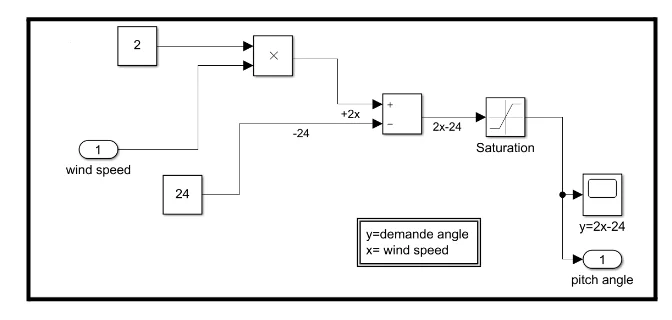
In figure 5, the minimum wind speed of the wind turbine is taken to be 12 m/s and the maximum wind speed for the wind turbine is set to 22 m/s set by the saturation block.
Fixed Wind Speed, Fixed Wind Direction
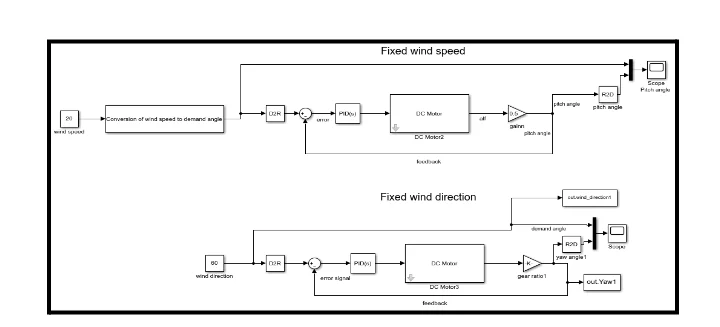
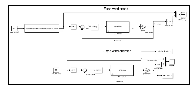
The system needs to be designed in 1st condition, provided that, the speed and direction of the wind are constant, so through the design, the system was assembled together as shown in figure 7, and the design was created that works on the analysis of the pitch and yaw angles. Completing the system with yaw and pitch control in series with a PID controller for tuning the system results in the model, shown in Figure 7.
PID controller
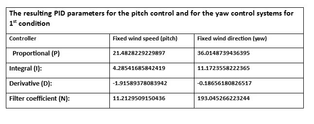

For a fixed wind speed of 20 m/s, the demand angle is 16 degrees, as shown in figure 6. The pitch angle, which is initially zero, is adjusted until it matches the demand angle, although it initially overshoots the demand angle value. The overshoot of the pitch angle and its response is due to the settings of the PID block, which was set to have an aggressive transient response behavior and a faster response. The transient response can be changed to robust to eliminate the overshoot, but this comes at the expense of response speed. Since wind is highly unpredictable, the pitch system should have a fast response to changes in wind therefore the aggressive model is more appropriate.

Similarly, in figure 8, an aggressive transient behavior is utilized, but fast response was preferred for the PID thus the yaw angle overshoots the demand angle before settling to the angle equal to the demand angle. It needs 7.08 seconds to settle the demand angle.
Fixed Wind Speed, Changing Wind Direction
A similar model to that shown in figure 14 was utilized for this subtask. The only change made to the model was to use a variable input as the input for wind direction, as shown below in figure 9 and figure 10 to indicate a changing wind speed so in 2nd condition the variable wind direction was selected as 129.6 degrees to analysis the yaw angle. The response for the fixed wind speed therefore is the same, as shown in figure 7. For the changing wind direction, the response is for yaw angle shown below in figure 11.
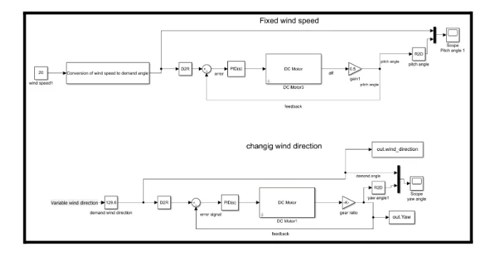

PID controller

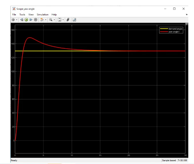
As it can be seen, when the wind direction changes from 60 degrees to 129.6 degrees, the settling time for the yaw angle increases from 7.08 seconds to 9.93 seconds. This can be explained by the increase in the rotation of the turbine and the settling time can be reduced by PID controller. Consequently, the yaw angle is controlled to follow the demand angle as illustrated in figure 12.

Variable wind speed, fixed wind direction
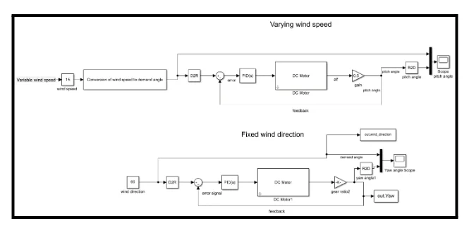
For a variable wind speed and fixed wind direction, the model in figure 6 was used again with the only difference being the use of a variable input instead of the constant block for the wind speed. Therefore, the response for the fixed wind direction is still similar to that in 1st condition shown in figure 16 but for the variable wind speed, the response is shown in figure 18.

PID controller


The minimum wind speed of the wind turbine is taken to be 12 m/s and the maximum wind speed for the wind turbine is set to 22 m/s, so for a variable wind speed here, it was assumed that, the wind speed was equal to 15 m/s second, resulting to that the demand angle was equal to 6 degrees. As a result, the response time of the Pitch angel decreased from 11.5 seconds, as it was in fixed wind speed to 6.11 seconds. The reason is that, the design of the system must be quick to respond, because the wind speed changes suddenly and unexpectedly. The pitch angle is hereby controlled to follow the demand angle of 15 m/s. The overshoot in the response is due to settings of the PID controller.
Justification
A wind turbine extracts power from the wind converts it into electricity. Wind is highly variable and its direction changes frequently. The response, I was looking for in my system is a fast response in order to keep up with the fast changes in wind properties. Secondly, I expected the response to have little oscillations both for the pitch and yaw control system to make the system stable. The system should therefore be properly damped. Finally, I was looking for a system, which follows the changes in the input signal with minimum errors during steady state operation. From the simulation results in Task II, all the requirements were met satisfactorily.
- 24/7 Customer Support
- 100% Customer Satisfaction
- No Privacy Violation
- Quick Services
- Subject Experts


