Advancements in Ultraprecision Machine Tool Design for Miniature
Abstract
Currently, the underlying necessities for predictability, producibility and productivity remain big issues in ultraprecision machining of miniature/micro products. The demand on rapid and economic fabrication of miniature/micro products with complex shapes has also made new challenges for ultraprecision machine tool design. In this paper, the design for an ultraprecision machine tool is introduced by describing its key machine elements and machine tool design procedures. The focus is on the review and assessment of the state-of-the-art ultraprecision machining tools. which can be vital for students seeking engineering dissertation help. It illustrates the application that promises to provide miniature/micro products. The trends in machine tool development, tooling, and machining processes are being pointed out. It also illustrates the application promise of miniature/micro products. The trends on machine tool development, tooling, workpiece material and machining processes are pointed out. Continue your journey with our comprehensive guide to Employee Engagement and Customer Satisfaction.
1. Introduction
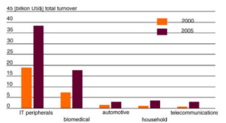
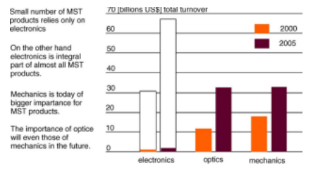
It is widely appreciated that the development of preci sion manufacturing has greatly changed our lives in terms of increased living standards. High precision manufacturing not only offers quality and reliability for conventional products, but also makes possible entirely new products, especially where mechatronics, miniaturization and high performance are important [1]. Impressive examples are digital cameras, mobile phones, minimal invasive medical equipment as well as biotechnological or chemical processing equipment [2]. The high function density and reduced size and weight will make the miniature and micro products more competitive. As the result the markets for miniature and micro components and products hold a high potential of growth [2].

Recently, new demands in the fabrication of minia ture/micro products have appeared, such as the manufacture of microstructures and components with 3D complex shapes
or free-form surfaces. It is found that those microstructures possess some special functions including light guiding, anti reflective and self-clean, etc. The microstructures will further improve the performance of miniature and micro products. Furthermore, fabrication of real 3D miniaturized structures and free-form surfaces are also driven by the integration of multiple functions in one product.
Currently, MEMS is one of major driving forces for making micro components. Silicon is a classical material for MEMS or Microsystems, but many other materials have meanwhile appeared for the increasing number of applica tions fields, which are becoming relevant for micro products. For examples, the life science as an emerging application area of MEMS requires glass, ceramics, metal and plastics rather than only silicon as raw materials of micro components.
Although traditional mechanical ultraprecision machin ing has be used as a major means to fabricate miniature and micro components/products, it still remains a big issue in the predictability, producibility and productivity of fabrication of miniature/micro products, especially for those miniature and micro components/products with complex surface forms/shapes. The ultraprecision machine tools design and machining technology will have to be changed so as to
achieve a rapid and economic fabrication of those compo nents and products in a variety of engineering materials and ensure the machines and technology easily accessible to the wider audience (including SMEs) of precision engineering.
The focus in this paper will be on the design of ultrapre cision machine tools especially for fabrication of miniature and micro components/products. The design guidelines for the machine and its key elements will be described and the start-of-the-art of the commercially available machines criti cally reviewed. The applications of micro fabrications will be illustrated and design of bench-type ultraprecision machines and their applications will be further explored. The papers will conclude with a discussion on the future trends in the subject area.
2. Design of ultraprecision machine tools
Fig. 1 illustrates a three-axis ultraprecision milling machine (UPM) 3, designed and built at the IPT in Aachen [3]. As other ultraprecision machine tools it consists of four major sub-systems. They are mechanical structure, spin dle and drive system, controller and system, and measure ment and inspection system. These sub-systems are essential, even though tooling and processing technologies are equally important.
2.1. Mechanical structure
Mechanical structure consists of stationary and moving bodies. The stationary bodies include machine base, column and spindle box housing, etc. They usually carry moving bod ies, such as worktables, slides, spindles and carriages.
The structural design is critical since the structure of a machine provides the mechanical support for all of the machine’s components. When considered in the context of the design of the machine as a system, some of the major design issues include [4]:
- • stiffness and damping;
- • structural configuration;
- • structural connectivity;
- • structure dynamic performance (such as thermal stability and response to external forces).
With regard to the proper functioning of moving axes and operational stability the structural design will follow the fol lowing principles:
• High structural loop stiffness: The structural loop includes the spindle shaft, the bearing and housing, the slideway and frame, the drives, and the cutting tool and work-holding fixtures. All mechanical components and joins in the prop agation path from the drive to the point of reaction, e.g. the end-effector (cutting tool) or the centre of gravity, must have a high stiffness to avoid deformation under changing loads [5].
• Good damping property: This can be achieved by choos ing high damping capability material as machine bed and slideway materials or filling structure’s cavities with lead shot and oil for viscous and mass damping or concrete for mass damping. Some methods, such as shear plate and tuned mass damper, can also be applied to damp structures [4].
• Symmetry and closed loop structural configuration: “T” configuration is popularly used for most of the ultra precision turning and grinding machines. Recently, a novel tetrahedron structure proposed by the NPL in England has been applied in an ultraprecision grinding machine—Tetraform C. It utilizes an internally damped space frame with all the loads carried in closed loop. The design generates a very high static stiffness coupled with exceptional dynamic stiffness [6].
• Thermal and elastic structural loops: Minimizing the influ ence of spatial thermal gradients in the system and making the system quickly reach and maintain a stable equilibrium.
• Minimization of heat deformation: Reduction of thermal deformation from the view point of the structural design

rather than the remedy by using the control technique. The methods include separating heat sources from the machine and processes, quickly expelling the heat gen erated within the machine and maintaining the fluid used for heat removal at a constant temperature, using zero or low thermal expansion materials. LODTM developed at LLNL employs several ingenious methods removing the heat-related errors. For instance, the LODTM is enclosed in a container within which the air temperature is main tained at 20 ± 0.010 ◦C. The measurement frame is made from Superinva and covered by a shell in which water maintained at 20 ± 0.001 ◦C is circulated. The housing for the main spindle bearing incorporates a coolant conduc tor in which temperature controlled water is circulated to remove any heat generated by bearings before it causes excessive deformation. As a result of these measures, the maximum drift due to heat deformation over a 24 h period is less than 25 nm [4].
• Isolation of environmental effects: Closed-machining envi ronment is essential to isolate the disturbances coming from outer circumstance surrounding the machine, e.g. vibrations from the floor, fluctuation of the room temper ature, heat transfer from other machines, floating dust and so on [7].
The choice of materials for a machine tool is one of key factors in determining final machine performance. Many cri teria may be considered, including temporal stability, specific stiffness, homogeneity, easiness of manufacturing and cost, etc. [5].
Cast iron and granite are most widely used materials for the machine base and slideways because of their good wear resistance, low thermal expansions, low stress-caused defor mation and high vibration damping capacity, albeit there is increasing usage of polymer concretes in the past few years. The drawback of granite is that it can absorb moister so it is used in dry environment. For this reason many builders seal the granite with epoxy resin. For obtaining light weight with high damping capacity and rigidity, polymer concrete becomes popular especially for some precision instruments and small sizes of machine tools. In some application cases, structural materials of low thermal expansion coefficient and
high dimensional stability have been used; among those are super-invar, synthetic granite, ceramics and Zerodur [8].
2.2. Work spindles
Spindle is a key element of the precision machine tool because the spindle motion error will have significant effects on the surface quality and accuracy of machined components. The most often used spindles in precision machine tools are aerostatic spindles and hydrostatic spindles. They both have high motion accuracy and capable of high rotational speed. An aerostatic spindle has lower stiffness than an oil hydro static spindle, but it has lower thermal deformation than oil hydrostatic spindle. Aerostatic spindles are widely used in machine tools with medium and small loading capacity while hydrostatic spindles are often applied in large heavy-load pre cision machine tools.
Recently, groove technique has been used in the design of air bearings. The grooved hybrid air bearing combines aero static and aerodynamic design principles to optimize ultra high speed performance. Aerostatic lift is generated by feed ing the bearing with pressurized air through orifice restric tors as in the conventional bearing design [9]. Aerodynamic lift is controlled by the additional helical grooves machined onto the shaft or bearing journal surfaces. The benefits of grooves in the bearing include significantly changing the pressure distribution within the bearing and improving load carrying capability and stiffness. The groove also changes the air velocity gradients in the bearing affecting the basic mechanism of whirl instability, which usually improves the threshold oat from which instability occurs [9].
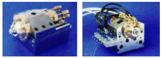
Fig. 2 shows the air bearing spindles developed by Fraun hofer IPT, Philips, Zeiss and Cranfield Precision for UPM 3 [10]. Combining the spiral groove technology with an exter nally pressurized bearing type, a maximum rotational speed of 100,000 rpm and radial stiffness of 30 N/ m are achieved in radial direction with a total error motion below 100 nm [10].
Air bearing slideways, air/magnetic bearing slideways, oil hydrostatic bearing slideways and air bearing rotary tables are widely used in the state-of-the-art ultraprecision machine tools as they are capable of high motion accuracy.
Oil hydrostatic bearings are often used in large machine tools because of their high load capability, although the additional pumping system, environmental and thermal issues need to be taken account of.
2.3. Drives
The moving mechanism is grouped into spindle and feed drives in machine tools. The spindle drive provides sufficient angular speed, torque and power to a rotating spindle held in the spindle housing with magnetic or air bearings. The elec tric AC motor and DC brushless motor for high speed spindles are always built into the spindle to reduce the inertia and friction produced by the motor-spindle shaft coupling. The air turbine spindle is also applied in ultraprecision machine tools.
The piezoelectric actuator is a kind of short stroke actuator. It is very promising for application in the rotary table drive and slideways drive because of its high motion accuracy and wide response bandwidth. Currently, piezo electric actuators have been applied in the design of the fine tool-positioner in order to obtain high precision motion of the cutting tool. The piezoelectric actuator combined with mechanical flexure hinge is often used for positioning control of the diamond cutting tool. More recently, Fast Tool Servo (FTS) system has been introduced for diamond turning components and products with structured and non-rotationally symmetric surfaces such as laser mirrors, ophthalmic lenses and lenses molds, etc. [11].
Linear motor direct drives and friction drives are two kinds of long stroke drives used on ultraprecision machine tools. Friction drive is very predictable and reproducible due to a prescribed level of preload at the statically determinate wheel contacts, thereby superior in machining optically smooth surfaces. One of the good applications of friction drives is on the UPM 3 with a friction wheel drive for X axis, which has form accuracy less than 0.2 m/100 mm as achieved [11]. Linear motor drives can offer the system designer an elegant alternative in that they produce linear motion directly and therefore eliminate the need for conversion mechanisms such as lead-screws, belt drives and rack and pinions, with poten tially better performance in terms of stiffness, acceleration, speed, smoothness of motion, accuracy and repeatability, etc. [28].
2.4. Control
The control sub-system includes motors, amplifiers, switches and the controller that are used to energize the elec trical parts in a controlled sequence and time. High speed, multi-axis CNC controllers are essential for efficient control of, not only servo drives in high precision position loop syn chronism for contouring, but also thermal and geometrical error compensation, optimized tool setting and direct entry of the equation of shapes (avoiding lengthy post-processing) [8]. By applying feedback control the control resolutions
in nanometer even sub-nanometer scales could be obtained. The use of advanced PC based control systems will be the trend for low cost ultraprecision machine tools in the future.
2.5. Metrology and inspection system
Metrology and inspection systems are the basis for ultra precision machining to be widely applied in industry. On the other hand, higher level accuracy assurance in metrology and inspection is also a drive for ultraprecision machining towards higher precision requested for future engineering industry. Fast and accurate positioning of the cutting tool towards the workpiece surface and monitoring of the tool conditions visually by the operator should be integrated into the inspection system especially for on-line operation purposes.
Laser metrology incorporated into the machine tool is widely used for feed and position control at the resolu tion down to nanometer or sub-nanometer level. Capaci tance gages, linear variable differential transducer (LVDT) and photoeletronic sensors are normally employed in the detection of nanometric displacement over small working distances [8].
Here it takes the laser interferometery metrology system as shown in Fig. 3, as a case study. Tool tip must be precisely
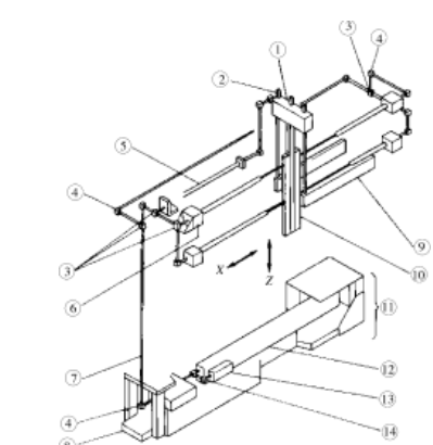
positioned in the X and Z directions. In order to satisfy Abbe’s principle, the laser interferometer shown in Fig. 3 is used for the tool position control. For the X direction, a pair of straightedges, one on each side of the tool bar, acts as the kinematic reference. To measure the position in the X direction, two beams are directed against each of the straightedges (i.e. a total of four beams). The tool bar’s pitch angle error is corrected using the upper and lower laser beams, while the mean value of the measurements from both sides is used to eliminate errors caused by axisymmetric expansion of the frame [12].
For measurements in the Z direction (the tool’s height), a pair of laser beams is directed against a pair of straightedges parallel to the tables as the kinematic reference. With a mirror attached to the bottom face of the tool bar (to get as close to the tool tip as possible), a third laser beam in the Z direction measures the tool’s position. The earlier pair of laser beams in the Z direction is used to eliminate errors of the tool bar rotating about the X axis [12].
In addition to incorporating Abbe’s principle, this laser interferometer has another special design for high precision measurement, i.e. the laser beam conduits contain a vacuum [12].
2.6. Main features of ultraprecision machine tools
The main features of an ultraprecision machine tool can be classified as:
• machine tool structure with high loop stiffness, high natu ral frequency and good damping characteristics; • high thermal and mechanical stability;
• low vibrations;
• high precision axis of motion;
• high precision control.
2.7. Design process for an ultraprecision machine tool
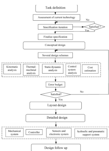
As illustrated in Fig. 4 the design of an ultraprecision machine tool requires five basic steps: task definition, conceptual design, layout design, detail design and design follow-up [4], albeit the full design process is always itera tive, parallel, non-linear, multidisciplinary and open-ended to any innovative and rational ideas and improvements. The purpose of task definition is to determine the machine functions and specifications. The functional requirements of an ultraprecision machine may address the considerations in geometric, kinematics, dynamics, power requirement, materials, sensor and control, safety, ergnomics, production, assembly, quality control, transport, maintenances, cost and schedule, etc. In this stage it needs to perform assessment of the state-of-the-art technology to make the design more competitive and the cost reasonable. The final specifications will be determined after several specification iterations. The following conceptual design is very important for the inno vation of the machine design. Brainstorming is the method
most often thought of for generating concept design [4]. Several design schemes may be proposed in this stage, which are followed by kinematics analysis, thermo-mechanic anal ysis, static analysis, dynamics analysis and control system analysis. The analysis results, together with error budget and cost estimation, will be used to check the conformance to the machine’s specifications and finally choose the best design scheme. Once a conceptual design is finished a design plan can be formulated for detail design. In detailed design stage it will finish the design of mechanical system design, controller, sensor and electronic system, electrical, hydraulic and pneumatic support system. After the detailed design is completed there is still much work that needs to be done in order to make the design successful, including develop a test and user support program, update design and documents, etc. [4]. The application needs and tooling and processing techniques applied are constantly the inputs to the design process.
3. Current ultraprecision machine tools
This section will briefly introduce several commercially available typical ultraprecision machine tools in the light of demonstrating the state-of-the-art of ultraprecision machine tools applied in the industry.
3.1. Diamond turning machines
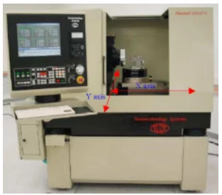
Single point diamond turning has long been a well established technology for the fabrication of a wide range of non-ferrous metals, crystals and polymers. Nanotch 350 UPL (Moore Nanotechnology System Ltd.) and Nanoform 350 (Precistech Ltd.) are two widely used diamond turning machines with 350 mm of swing capability. Here, it takes Nanoform 350 UPL as an example to explain its configu ration. This two-axis ultraprecision lathe is characterized as “T” axis configuration. As shown in Fig. 5 the X slide moves spindle box along X direction, while diamond cutting tool is moved along Z direction by Z slide [13]. Both slides are built on the machine base and vertical to each other. They are also in the same height so as to improve motion accuracy. Nanotech 350 UPL employs high stiffness hydrostatic slideways, state-of-the-art linear motors with sinusoidal drive amplifiers and a 6000 rpm heavy-duty groove compensated air bearing work spin dle with liquid cooling for long-term thermal stability [14].
With Nanotech 350UPL components used in the electro optics, aerospace, consumer electronics and computer industries can be machined with good surface finish (in several nanometres) and high form accuracy (in tens of nanometres). Nanotech 350 UPL has optional grinding system for micro-grinding optical components and direct grinding of lens molds in non-diamond machinable materials such as metals and ceramics.
3.2. Diamond grinding machines
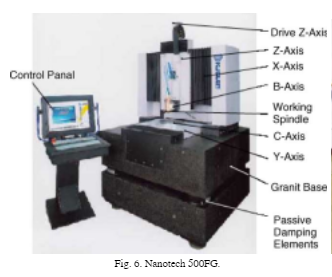
Diamond grinding allows access to more materials than diamond turning. It is capable of fabrication of a range of materials including optical glass, crystals, ferrous metals, polymers and ceramics. Nanotech 500FG (Moore Nanotech nology System Ltd.) is a typical multi-axis diamond grinding machine. It is capable of generating arbitrary conformal opti cal surface (including non-spherical and non-axisymmetric) shapes within a 250 mm × 250 mm × 300 mm machining envelope. As shown in Fig. 6, Nanotech 500FG has three linear axes. They are the independently mounted X and Z axis with a “T” configuration and Y axis mounted integral to Z axis to eliminate “stacked” axes. The slideways stiffness is 350 N/ m. The motion accuracy of work spindle is lower than 50 nm. Rotary table (B axis) is used to carry
the grinding spindle. When replacing the grinding spindle with a diamond tool, the machine is also capable of turning operations [15].
Nanotech 500FG is capable of generating components with non-axisymmetric and axisymmetric geometrics, such as conformal optics with spherical, aspherics, cylindri cal, conical geometries; lenses and mould inserts; F-Theta Lenses; aspheric lenses and mirrors; diffractive element; polygons and prisms [15].
To pursue a more rigidity structure an ultraprecision grinding machine—PicoAce machine with novel pyramidal space frame structure was commissioned by Loadpoint Ltd. recently. PicoAce is suitable for traverse grinding of flat or convex work surfaces up to a maximum of Ø 305 mm diame ter or plunge grinding of flat surfaces to a maximum diameter of Ø 200 mm. The general arrangement of PicoAce is shown
in Fig. 7 [16], the principal machine elements: cup wheel grinding spindle, rotary work table, X and Z slideways are mounted in a closed loop structure. The structure takes the form of a pyramid shape frame fixed to a solid rectangular base. The cup wheel spindle has a vertical axis and is arranged to slide up and down in a cylindrical Z slideway positioned centrally over the base. Directly beneath the wheel spindle is the rotary table mounted on the X slidway. With this novel structure the static loop stiffness of PicoAce is 100 N/ m in vertical direction. High motion resolution of 1 nm is achieved in Z axis. It can produce optical quality surface finishes with low levels of subsurface damage on a range of hard and brittle materials [16].
3.3. Micro-milling machines
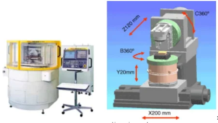
Kugler MICROMASTER MM® is a high-precision CNC controlled five-axis milling machine. It is developed by the
Fraunhofer IPT in Aachen and Kugler Ltd. to meet the special demands and requirements of micro machining and mechan ical microstructuring. Its configuration is shown in Fig. 8. MICROMASTER MM is equipped with hydrostatic linear guides to improve the stiffness and damping characteristics. Two of slides (X and Y) are driven by linear motors to avoid a mechanical coupling between feed drive system and moving components, high resolution linear scales are integrated into these axes. Two additional rotary axes (B and C axes) enable a real five-axis milling to be carried out on the machine [3].
The machine is based on fine-grained granite which ensures highest long-term stability. A pneumatic vibration insulation system is used to effectively suppress oscillations with fre quencies in the range >5 Hz. Depending on the choice of machining spindles and tools, a variety of non-ferrous metals, brittle and hard materials can be processed with high preci sion. The arbitrarily programmable CNC-control for process sequences and machining paths also enables the manufac turing of microstructure and free-form surfaces with almost optical quality [17].
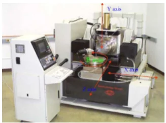
Fanuc Robonano -0iA is another well-known five-aixs milling machine. The machine configuration is shown in Fig. 9 [18]. The work rotary table (Baxis) is carried by X slide. Y slide is for vertical movement, which strokes 20 mm. Z slides can move the milling cutting system in a direction nor mal to theX–Y plane. The Robonano machine is characterized with the friction-free servo mechanism as aerostatic bear ings are employed in the translational and rotary axes. The

aerostatic slideways are connected through floating nut slide mechanism to aerostatic leadscrew. One nanometer position ing and smooth feed are realised by the 64 million pulse encoders and aerostatic bearing AC servo motor. Another character of the Robonano machine is the high speed air turbo spindle and high precision chucking mechanism. In Robo nano machine high speed air turbine spindle with a diamond milling tool, driven by air, is set on the B or C axes table. The side of both ends of the turbine blade and the radial part of the spindle shaft are supported from aerostatic bearings. A piezo electric device is built in between the spindle and a bracket to control the position of cutting edge minutely. Because tur bine drives only develop useful power over a narrow range and the machine uses three spindles to cover a wide speed range (20,000–100,000 rpm). Robonano machine has been applied in 3D precision machining and optics mould manu facturing (moulds for diffraction grating and aspheric lenses) [18].
of light (light trap) through increase of active surfaces [10].
Ultraprecision machining can efficiently manufacture micro-mechanical components, such as micro-sensor (pressure, flow and gas), micro-actuator, micro-motors, micro-pump, micro-valves, encoder disks and fiber optic mechanical components, etc. Fig. 13 shows a spherical end face of a fiber optic connector, which is ground by using resin
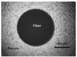
bond diamond cup wheel [21]. The average surface rough ness Ra is 6.9 nm in the fiber area on the connector, while the surface roughness of the ground ferrule (Zirconia) is 30 nm.
Using single point diamond turning and diamond grind ing many micro-optical components can be machined with high form accuracy and good surface finish. These optical components include micro-optics such as camera lens, CCD lens; free-form optics such as ophthalmic lenses, scanner mir rors, prisms; retro-reflectors used for street sign, warning sign and clothing; displays for mobile phones, TFT panel, etc. Fig. 14 shows a surface-structured mirror turned by Fast Tool Servo on an ultraprecision lathe [11].
The surface of the mirror consists of a rotationally symmetrical part on which a Fig. 12. Silicon wafer structuring. of light (light trap) through increase of active surfaces [10]. Ultraprecision machining can efficiently manufacture micro-mechanical components, such as micro-sensor (pressure, flow and gas), micro-actuator, micro-motors, micro-pump, micro-valves, encoder disks and fiber optic mechanical components, etc. Fig. 13 shows a spherical end face of a fiber optic connector, which is ground by using resin Fig. 13. Ground spherical end faces of fiber optic connector. non-rotationally symmetrical surface with 90 facets is super imposed. The mirror is used as an integrator optic to enhance the beam quality in high power lasers [11]. The indispensable advantage of single point diamond turning, micro-milling and nano-grinding are applicable on manufacture of 3D complex shape/form micro moulds, dies
and embossing tooling for mass production of optical and mechanical parts. In fact, this should be the focus of micro machining. It is anticipated that micro machining will be intensively used in the fabrication of compressive moulds and injection moulds. Fig. 15 shows an injection moulding tool for matchmaking machined by micro-milling [22]. The material of the mould is hardened steel (54 HRC), its posi tion and form tolerance at workpiece is ±5 m, and surface finish Ra > 0.25 m. The diameter of smallest milling cutter is 0.2 mm. The total machining time is 50 min [22].
5. Trends in the fabrication of miniature and micro products
Machining accuracy and high quality surface generation depend on machine tool accuracy, tooling, workpiece mate rial and operational factors which are well applicable in manufacture of miniature and micro components and prod ucts.
5.1. Trends of ultraprecision machine tools
The trend in ultraprecision machining will be cutting down machining cost while maintaining high accuracy. However, so far most of micro machining is undertaken using conven tional size ultraprecision machine tools. This will of course increase the investment and operation costs, which make the manufacturing SMEs difficult access the high-value added technology/business. Development of bench-type ultrapreci sion machine tools and the associated nano–micro machining technology may lead to wider application of ultraprecision machining technology and their application in fabrication of miniature and micro components/products in particular.
The benefits of the bench-type machines may include:
• low machine production costs;
• small space and energy-efficient;
• ease of localized environmental control (temperature and vibrations, etc.) and friendliness and thus low operation costs;
• affordable manufacturing technology.
Fig. 16 illustrates the design layout of a bench-type micro milling machine, which is currently being developed by the authors with the support of the EU MASMICRO project [30]. The machine aims at manufacturing the miniature and micro components in various engineering materials, such as:
(1) MEMS (Si)
• complex microstructures and
• micro-grooves.
(2) Optical components (Glass, polymer, Al) • complex shape or freeform optics (lenses, mirrors, prisms) and
• lens shutters, displays, light guiding microstructures.
(3) Medical components (polymer, glass)
• ophthalmics (contact lens) and
• dentistry.
(4) Mechanical components (Al, steel)
• microsensors (pressure, flow, gas) and
• fiber optic-mechanical components (filter, wave plates).
(5) Moulds (high strength Al, copper alloy, steel) • mould for optics lenses and fiber optic element and • mould for reflective foils.
5.2. Tooling
Diamond cutting tool is popularly used in ultraprecision machining for its high thermal conductivity, high hardness and wear resistance and high elastic and shear moduli, which reduce tool deformation during machining. Cutting edge sharpness is crucial to the machined surface quality.
The crystalline structure of the diamond enables very sharp cutting edge to be produced. Now a cutting edge in tens of nanometers can be achieved. In addition, special tool for turning may be needed for some complex surfaces. One example is the half radius diamond cutting tool for machining large steps diffractive mirrors.
Diamond micro-milling can be used to machining microstructures. In Fraunhofer IPT diamond endmill with a diameter of 300 m has been used for the manufacturing of micro-grooves. An adjustable diamond ball-end mill is used for the fabrication of sculptured surface geometries with opti cal surface qualities [3].
If an optical surface quality is not required, other types of tools can be used. As shown in Fig. 18 the micro-milling tools are made from tungsten carbide with Ø 0.2–1.5 mm in diameter. Much work has also been carried out in develop ing CVD coatings for better wear resistance and improved thermal properties, etc. [24].
Nano-grinding using metal bond or resin bond diamond wheels or CBN wheels has been extensively applied for fabrication of glass or ceramic optics. The theoretical and
experimental studies on nanometric diamond grinding of glasses show that the average grain size of the wheel is the most significant factor affecting the machined surface roughness. If the wheel with average grain size less than 10 m is used, the grinding of optical glasses in ductile mode can be obtained and the crack will be removed in the well controlled process [25]. Recently, some work has been undertaken using the CVD coating for single or multi-layer, micro abrasive tools. Fig. 19 shows a very small abrasive
pencil manufactured by coating cemented carbide shanks with a CVD layer [26]. The main advantages of these micro abrasive tools are flexible shape and the small diamond grain size of approximately 2–12 m [3]. Hence the ductile grinding mode could be achieved. Using these tools different hard and brittle materials such as silicon, aluminium oxide, ceramics and glasses have been successfully ground with high surface quality achieved [3].
In micro machining the minimum feature size is limited by the tool size. With such a mall tool the mechanical stability of the micro tool itself will be crucial for maintaining the product accuracy. Therefore, the tendency in the study of micro tooling seems to be:
• fabrication methods for minimizing micro tooling; • optimization of the geometric and coating properties of micro tooling in order to improve tool life and the process accuracy;
• tool holding and balancing as well as micro tool setting device;
• micro tooling characterization (machinability in particu lar);
• tool condition monitoring during the process.
5.3. Workpiece materials
Workpiece material properties will play an important role in micro machining. The tendency in the study of workpiece materials will be:
• Size effects and microstructure effects in the micro machining process.
• Machinability of a variety of engineering materials and new composite materials, such as glasses, ceramics, met als, plastics, polymers and carbon fiber composites.
• Work holding, i.e. stiff clamping within minimum distor tion of the workpiece and the difficulty in handling of miniature and micro sized components [8].
5.4. Machining processes
Micro machining is influenced by mechanical, thermal and chemical loading in the machining contact zone. It is needed to develop a more complete understanding of those loadings on the machining process and the quality of the sur faces generated. In addition, the micro machining process has to become economically reasonable and mass manufac ture approach has to be investigated.
The tendency in the study of the machining process will be, but not limited to:
• Multiscale modelling approach (finite element analysis combined with molecular dynamic simulation) for a bet ter understanding of the process and surface generation [27,29].
• Optimizing the machining process and its variables.
• Controlling the machining process in respect of the pro ducibility, productivity and predictability.
6. Concluding remarks
The markets for miniature and micro products, especially for those with microstructures and free-form surfaces, hold a high potential of growth. Traditional mechanical ultra precision machining can be utilized to fabricate miniature and micro components and products with complex shapes in a more controllable way. The indispensable advantage of ultraprecision machining is its applicability to manufacture 3D complex components/devices including micro moulds, dies and embossing tooling for mass production of opti cal and mechanical components. It also provides a cost effective solution for low volume production or prototyping of MEMS. Machining accuracy depends on machine tool accuracy, tooling, workpiece material and operational factors. The performance of ultraprecision machine tools depends on the accuracy of key elements, including work spindles and motion axes. Bench-type ultraprecision machines will be one of the future development tendencies since they may enable ultraprecision machining of miniature and micro products economically and thus the technology affordable for wider audience of manufacturing SMEs. Efforts will also need to be made on the methods for micro tooling fabrication, handling of micro tools and components, tools and components hold ing and fixturing, and tool condition monitoring during the process. Studies on machinability of a variety of engineering materials and multiscale modelling approach are also needed in order to gain better understanding of the mico machining process.
Acknowledgements
The authors would like to thank the partners within the EU 6th Framework IP MASMICRO consortium/project (Con tract No.: NMP2-CT-2004-500095-2) and particularly the partners in its RTD five sub-group for the stimulating dis cussions and meetings, which are very helpful in forming this paper.
References
- [1] P.A. McKeown, From micro-to nano-machining-towards the nanome tre era, Sens. Rev. 16 (2) (1996) 4–10.
- [2] B. Wybranski, Micro production technologies, mstNews 2 (2004) 43–45.
- [3] M. Weck, Ultraprecision machining of microcomponents, Mach. Tools (2000) 113–122.
- [4] A.H. Slocum, Precision Machine Design, Englewood Cliffs, Prentice Hall, 1992.
- [5] P. Schellekens, N. Rosielle, Design for precision: current status and trends, Ann. CIRP 47 (2) (1998) 557–584.
- [6] D.J. Stephenson, D. Veselovac, S. Manley, J. Corbett, Ultra-precision grinding of hard steels, Precision Eng. 15 (2001) 336–345.
- [7] H. Shinno, H. Hashizume, Y. Ito, C. Sato, Structural configuration and performances of machining environment-controlled ultraprci sion diamond turning machine ‘capsule’, Ann. CIRP 41 (1) (1992) 425–428.
- [8] N. Ikawa, R.R. Donaldson, R. Kormanduri, W. KOnig, T.H. Aachen, ¨ P.A. Mckeown, T. Moriwaki, I.F. Stowers, Ultraprecision metal cutting—the past, the present and the future, Ann. CIRP 40 (2) (1991) 587–594.
- [9] P. Stanev, F. Wardle, J. Corbett, Grooved hybrid air bear ings, http://www.loadpoint.co.uk/site2/grooved.pdf (accessed on 8th December 2003).
- [10] B. Leifheim, Precision and ultraprecision machine tools. Euspen online lecture, http://www.euspen.org/training/lectures/ course2free2view/03PrecisionUltraTool/demolecture.asp (accessed on 8th December 2003).
- [11] M. Weck, S. Fischer, M. Vos, Fabrication of microcomponents using ultraprecision machine tools, Nanotechnology 8 (1997) 145– 148.
- [12] H. Nakazawa, Principles of Precision Engineering, Oxford University Press, New York, 1994.
- [13] B. Cassin, Recent C & B Axis Development from Moore Nanotech nology Systems, LLC, http://www.nanotechsys.com/images/PDFs/ RecentC&BAxisDevelopments.PDF (accessed on 30 March 2005).
- [14] Nanotech 350 UPL Brochure, Moore Nanotechnology Systems Ltd., http://www.nanotechsys.com (accessed on 15 March 2005). [15] Nanotech 500 FG brochure, Moore Nanotechnology Systems Ltd., http://www.nanotechsys.com (accessed March 2005).
- [16] PicoAce brochure, Loadpoint Ltd., http://www.loadpoint.co.uk/ picoace/picoace.htm (accessed on 5th January 2004).
- [17] 5-Axis Machining Center Micromaster® MM, Kugler Company Brochure, www.kugler-precision.com (accessed on December 2003).
- [18] Robonano -0iA brochure, Fanuc Ltd., http://www.fanuc.jo/en/ product/robonano (accessed on 12th December 2003).
- [19] O. Rubenach, Micro Technology—Applications and Trends, Euspen ¨ Online Training Lecture, http://www.euspen.org/training/lectures/ course2free2view/02MicroTechApps/demolecture.asp (accessed on 18th December 2003).
- [20] A. EI-Fatatry, A. Correial, Nanotechnology in microsystems: poten tial influence for transmission systems and related applications, mst News 3 (2003) 25.
- [21] H. Huang, W.K. Chen, L. Yin, Z. Xiong, U.C. Liu, P.L. Peo, Micro/meso ultraprecision grinding of fibre optic connectors, Pre cision Eng. 28 (1) (2004) 95–105.
- [22] KERN Micro- und Feinwerktechnik GmbH & Co. KG, http://www.kern-microtechnic.com (accessed on 23rd March 2005). [24] J. Webster, M. Tricard, Innovations in abrasive products for precision grinding, Ann. CIRP 53 (2) (2004) 597–642.
- [25] M. Chen, D. Li D, S. Dong, F. Zhang, Factors influencing the surface quality during ultra-precision grinding of brittle materials in ductile mode, Key Eng. Mater. 257–258 (2003) 201–206.
- [26] J. Gabler, H.-W. Hoffmeister, B. Menze, L. Schafer, Micro-abrasive pencils with CVD diamond coating, Diamond Relat. Mater. 13 (3–7) (2003) 707–710.
- [27] X. Liu, R.E. Devor, S.G. Kapoor, The mechanics of machining at the microscale: assessment of the current start of the science, Trans. ASME: J. Manuf. Sci. Eng. 126 (2004) 666–678.
- [28] Accessed on 9th May 2005 http://www.rockwellautomation.com/ anorad/products/linearmotors/.
- [29] X. Luo, K. Cheng, R. Holt, An investigation on the mechanics of nanometric cutting and the development of its test-bed, Int. J. Prod. Res. 41 (7) (2003) 1149–1165.
- [30] Accessed on 9th May 2005 www.masmicro.net.
Take a deeper dive into 360 Degree Feedback and Evaluation Form with our additional resources.


- 24/7 Customer Support
- 100% Customer Satisfaction
- No Privacy Violation
- Quick Services
- Subject Experts